Before using your air conditioner, please read this manual carefully and keep it for future reference. INVERTER SPLIT TYPE ROOM AIR CONDITIONER SERIES Please read this installation manual completely before installing the product. If the power cord is damaged, replacement work shall be performed by authorised personnel only. Installation work must be performed in accordance with the national wiring Standards by authorised personnel only.
CONTENTS SAFETY PRECAUTIONS Warning .....................................................................................................................................2 Caution ......................................................................................................................................2 INSTALLATION INSTRUCTIONS Selecting installation place.........................................................................................................3 Accessories ........ ..............
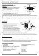
SAFETY PRECAUTIONS Read the follow SAFETY PRECAUTIONS carefully before installation. Installation must be performed in accordance with the requirement of NEC and CEC by authorized personnel only. Incorrect installation due to ignoring of the instruction will cause harm or damage, and the seri ousness is classified by the following indications. WARNING This symbol indicates the possibility of death or serious injury. CAUTION This symbol indicates the possibility of injury or damage to property.
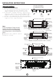
INSTALLATION INSTRUCTIONS More than 15cm/5.9in (to the ceiling) Selecting installation place Read completely, then follow step by step. More than More than Indoor unit 12cm/4.72in 12cm/4.72in Do not expose the indoor unit to heat or steam. Select a place where there are no obstacles in front or around the unit. Make sure that condensation drainage can be conveniently routed away. More than 2.3m/7.55ft Do not install near a doorway. (from the floor) Ensure that the space on the left and right Fig.
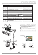
INSTALLATION INSTRUCTIONS Accessories Q’ty 1 Name of Accessories Installation Plate 2 Clip Anchor 5-8(depending on models) 3 Self-tapping Screw A ST3.9X25 5-8(depending on models) 4 Seal (For cooling & heating models only) 1 5 Drain Joint (For cooling & heating models only) 1 6 Remote controller 1 7 Self-tapping Screw B ST2.
INSTALLATION INSTRUCTIONS Correct orientation of Installation Plate Indoor unit installation 1. Fit the Installation Plate 1. F i t t h e i n s t a l l a t i o n p l ate horizontally o n s t r u c t u r a l p a r t s o f the wall with s p a c e s a r o u n d t h e i n s t allation plate. 2. I f t h e w a l l i s m a d e o f b rick, concrete or t h e l i k e , d r i l l f i v e o r eight 5mm/0.197in d i a m e t e r h o l e s i n t h e wall.
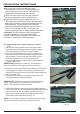
INSTALLATION INSTRUCTIONS Wall 2. Drill a hole in the wall Outdoor Indoor 5-7mm /0.2-0.28in 1. Determine hole positions according to the diagram detailed in Fig.5. Drill one (1) hole (φ90mm/3.54in) slanting slightly to outdoor side. 2. Always use wall hole conduit when drilling metal grid, metal plate or the like. Fig.6 3. Drainage Installation Drainage 1. Run the drain hose sloping downward. Do not install the drain hose as illustrated in Fig.7. 2.
INSTALLATION INSTRUCTIONS Do not smoke during the installation work. The equipment must never be operated without the refrigerant lines connected, otherwise the equipment will be damaged immediately. The screw connections may only be tightened using the appropriate open-ended spanner. Remember that if they are tightened with too little torque they will leak but if they are tightened with too much torque, the screw connections may suffer damage.
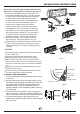
INSTALLATION INSTRUCTIONS Note: Route the package of pipes/hoses in the direction of (rear)right or (rear)left. See Fig.13 . 1.Both sides drainage structure is standard. For both sides drainage structure, it can be choosen for right, left or both sides drainage connection. If choosing both sides drainage connection, another proper drain hose is needed as there is only one drain hose offered by factory. If choosing one side drainage connection, make sure the drain hole on the other side is well plugged.
INSTALLATION INSTRUCTIONS Outdoor unit installation Outdoor unit 1. Outdoor installation precaution Select the location for installation(follow the previous notes on selecting the installation place). If the outdoor unit is higher thanthe indoor unit, make sure that a curve is made in the refrigerant pipe which is lower than the bottom edge of the indoor unit. See Fig.16.
REFRIGERANT PIPE CONNECTION 4. Connecting the refrigerant pipe to outdoor unit CAUTION: For your safety, always wear goggles and work gloves when connecting the pipes. NOTE: To distinguish the connectors to be connected to the indoor unit and outdoor unit, the connectors of the refrigerant pipe has been labelled “A”, “B”,“C”and “D”. Ensure the marks on the , , connector are the same to the indoor s and outdoor s respectively during connection. 1.
REFRIGERANT PIPE CONNECTION Coupling size (last 2 part numbers) Pound-force foot(1bf-ft) Newton meter(N-m) Kilogram-force meter(kgf-m) -06(9.5mm/3/8 dash size) 18 - 20 24.4 - 27.1 2.4 - 2.7 -08(12.7mm/1/2 dash size) 30 - 35 40.6 - 47.4 4.1 - 4.8 -12(19.1mm/3/8 dash size) 45 - 50 61.0 - 67.7 6.2 - 6.9 -16(25.4mm/1 dash size) 60 - 65 81.3 - 88.1 8.2 - 8.9 After completing steps 1- 4, check that all the connections are sealed correctly using leak detection spray or soap suds.
ELECTRICAL WORK CAUTION CAUTION CAUTION CAUTION After the confirmation of the above conditions, prepare the wiring as follows: 1) Never fail to have an individual power circuit specifically for the air conditioner. As for the method of wiring, be guided by the circuit diagram posted on the inside of control cover. 2) The screw which fasten the wiring in the casing of electrical fittings are liable to come loose from vibrations to which the unit is subjected during the course of transportation.
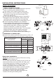
ELECTRICAL WORK Front Panel Connect the cable between indoor unit and outdoor unit Electronic box cover NOTE: Before performing any electrical work, turn off the main power to the system. 1. The connection cables of indoor and outdoor units have been connected to the terminals on the control board except the grounding wire(Y/G), only white plug connectors exposed. See Fig.27. 2. Remove the control cover from the outdoor unit by loosening the screw. 3.
TEST RUNNING Test running Perform test operation after completing gas leak check at the flare nut connections and electrical safety check. Check that all tubing and wiring have been properly connected. Check that the gas and liquid side service valves are fully open. 1. Connect the power, press the ON/OFF button on the remote controller to turn the unit on. 2. Use the MODE button to select COOL, HEAT, AUTO and FAN to check if all the functions works well. 3.
The Klimaire logo is a registered Trademark of Klimaire Products inc. Copyright 2010 Klimaire Products Inc. 2190 NW 89 Place, Doral, FL 33172 - USA Tel: (305)593-8358 Fax (305) 675-2212 www.klimaire.com sales@klimaire.com The design and specifications are subject to change without prior notice for product improvement. Consult with the sales agency or manufacturer for details.