
Installation Manual


9
Select the location for installation(follow the previous
notes on selecting the installation place).
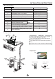
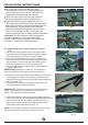
If the outdoor unit is higher thanthe indoor unit,
make sure that a curve is made in the refrigerant
pipe which is lower than the bottom edge of the
indoor unit. See Fig.16.
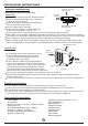
In the case that the installation place is exposed to
strong wind such as a seaside, make sure the fan
operating properly by putting the unit lengthwise
along the wall or using a dust or shield plates, Fig.17.
If need suspending installation, the installation
bracket should accord with technique requirement
in the installation bracket diagram. The installation
wall should be solid brick, concrete or the same
intensity construction, or actions to reinforce,
damping supporting should be taken. The connection
between bracket and wall, bracket and the air
conditioner should be firm, stable and reliable.
Be sure there is no obstacle which block radiating air.
Strong
wind
Fig.17
Outdoor unit installation
1. Outdoor installation precaution
2. Settlement of outdoor unit
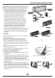
Anchor the outdoor unit with a bolt and nutφ10 or φ8
tightly and horizontally on a concrete or rigid mount.
Outdoor unit
Refrigerant pipe
Indoor unit
Curve
Fig.16
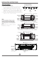
Fig.18
Fig.19
Drain joint installation
Seal
Drain joint
Base pan hole of
outdoor unit
Seal
Drain pipe
(A)
(B)
For the drain joint with the seal(Fig.19 (A)), first fit the
seal onto the drain joint, then insert the drain joint
。
into the base pan hole of outdoor unit, rotate 90 to
securely assemble them. To install drain joint as
shown in Fig.19 (B), insert the drain joint
into the base pan hole of outdoor unit until it remains
fixed with a clicking sound. Connecting the drain
joint with an extension drain hose (Locally
purchased), in case of the water draining off the
outdoor unit during the heating mode.
NOTE: The drain joint is slightly different according
to the different outdoor unit.
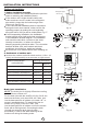
Outdoor unit dimension
mm/in(WxHxD)
A(mm/in)
B(mm/in)
530(20.87)
290(11.42)
624(24.57)
560(22.05)
366(14.41)
335(13.19)
549(21.61)
458(18.03)
276(10.87)
276(10.87)
Mounting dimensions
780(30.71)x540(21.26)x250(9.84)
760(29.92)x590(23.23)x285(11.22)
660(25.98)x242(9.52)x540(21.26)
990(38.98)x965(37.99)x345(13.58)
840(33.07)x700(27.56)x320(12.6)
A
W
B
D
Air inlet
Air outlet
Air inlet
INSTALLATION INSTRUCTIONS
523(2 0.59)
340(1 3.39)
820(3 2.28)x 595(23 .43)x330(12.99)