
Installation Manual


11
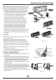
Coupling size (last 2 part numbers)
Pound-force foot(1bf-ft)
Newton meter(N-m)
Kilogram-force meter(kgf-m)
18 - 20
30 - 35
45 - 50
60 - 65
24.4 - 27.1
40.6 - 47.4
61.0 - 67.7
81.3 - 88.1
2.4 - 2.7
4.1 - 4.8
6.2 - 6.9
8.2 - 8.9
-06(9.5mm/3/8 dash size)
-08(12.7mm/1/2 dash size)
-12(19.1mm/3/8 dash size)
-16(25.4mm/1 dash size)
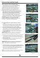
After completing steps 1- 4, check that all the
connections are sealed correctly using leak
detection spray or soap suds. If any bubbles form,
the system has a leak and the screw connectors
must be retightened using an open-ended spanner.
5. Now remove the cover on the top valve using a
19 mm open-ended spanner. Open the valve by
turning it counter-clockwise as far as it will go
using a 5 mm Allen key. The valve is now open. If
the valve is not opened fully, the system may
malfunction and suffer damage. Screw the cover
back on to the top valve and tighten it well to
ensure that it is properly sealed. See Fig.24.
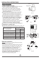
6. Now remove the cover on the bottom valve using
a 19 mm open-ended spanner. Open the valve by
turning it counter-clockwise as far as it will go
using a 5 mm Allen key. The valve is now open.
If the valve is not opened fully, the system may
malfunction and suffer damage. Screw the cover
back on to the bottom valve and tighten it well to
ensure that it is properly sealed. See Fig.25.
Important! The conical ring on the valve has an
important sealing function together with the sealing
seat in the caps. Ensure that you do not damage the
cone and that you keep the cap free of dirt and dust.
7. After completing steps 1- 6, check that all the
connections are sealed correctly using leak
detection spray or soap suds. If any bubbles form,
the system has a leak and the screw connectors
must be retightened using an open- ended spanner.
8. Start the equipment so that the operating
pressures build up inside it. Check all the
connectors again for signs of leaks
a) during cooling mode
b) in heating mode.
If any bubbles form, the system has a leak and the
screw connectors must be retightened using an
open-ended spanner.
Fig.25
Fig.24
REFRIGERANT PIPE CONNECTION