
Installation Manual


4
INSTALLATION INSTRUCTIONS
.
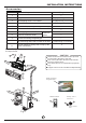
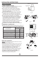
Accessories
Note: Except the above parts provided, the other parts needed during installation you
must purchase.
Fig.3
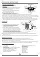
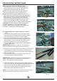
Use a stud finder to locate studs to prevent
unnecessary damage to the wall.
Two of the A, B and C directions should be
free from obstructions.
This illustration is for explanation purposes
only.
Copper lines must be insulated independently.
CAUTION
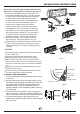
Mounting screw B
ST2.9x10-C-H
Remote controller
holder
7
8
Remote Controller
6
Quick connecting
refrigerant pipe
Self-tapping Screw B ST2.9X10
Remote controller
Installation Plate
Name of Accessories
Self-tapping Screw A ST3.9X25
Seal(For cooling & heating models only)
Drain Joint(For cooling & heating models only)
Clip Anchor
Number
Q ty’
Remote controller holder
9
10
11
1
2
3
4
5
6
7
8
1
1(depending on models)
2
1
5-8(depending on models)
5-8(depending on models)
1
1
1
2
1
Quick connecting refrigerant pipe
Optional
parts
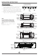
>12cm/4.72in
Air Filter
>12cm/4.72in
>15cm/5.9in
1
2
3
>2.3m/7.54ft
Air freshening filter(used to install on Air filter)
Sound deadening pads(used to wrap up the
quick connectors)
ON/OF F
MODE
FAN
TEMP
SHORT
CUT
TIMER ON
TIMER OFF
SLEEP
SWING DIRECT
LED
TURBO
C
B
A
60cm above
60cm above
30cm above
200cm above
Air Outlet
30cm above