
Installation Manual


5
INSTALLATION INSTRUCTIONS
Indoor unit installation
Fig.4
Fig.5
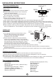
Note:
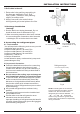
1. Fit the Installation Plate
1. Fit t h e i nstalla t i on plate ho r i zontall y
on str u c tural par t s o f the wall wi t h
spac e s a round the i n s tallati o n p late.
2. If th e w a ll is made of b r i ck, concr e t e or
the li k e , drill fiv e o r e ight 5mm/ 0 . 197in
diam e t er holes in t h e w all. Inse r t C lip
anch o r f or approp r i ate mount i n g screws.
3. Fit t h e i nstalla t i on plate on t h e w all with
eigh t o r f ive type A sc r e ws.
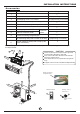
Correct orientation
of Installation Plate
Fit the Installation Plate and drill
holes in the wall according to the
wall structure and corresponding
mounting points on the installation
plate.
(Dim e n sions are i n m m /in unles s
othe r w ise state d )
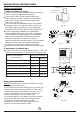
Right rear side
refrigerant pipe
hole φ90/3.54in
Right rear side
refrigerant pipe
hole φ90/3.54
Left rear side
refrigerant
pipe hole
φ90/3.54in
Left rear side
refrigerant
pipe hole
φ90/3.54in
Left rear side
refrigerant
pipe hole
φ90/3.54in
Left rear side
refrigerant
pipe hole
φ90/3.54in
Indoor unit outline
Indoor unit outline
150mm/5.91in or more to ceiling
150mm/5.91in or more to ceiling
150mm/5.91in or more to ceiling
150mm/5.91in or more to ceiling
120mm/4.72in
or more to wall
120mm/4.72in
or more to wall
120mm/4.72in
or more to wall
120mm/4.72in
or more to wall
120mm/4.72in
or more to wall
120mm/4.72in
or more to wall
120mm/4.72in
or more to wall
36.5
41
9000Btu/h models(A:680/26.77, B:255/10.04, C:170/6.69, D:92/3.62)
12000Btu/h models(A:770/30.31, B:255/10.04, C:170/6.69, D:95/3.74)
18000Btu/h models(A:905/35.63, B:275/10.83, C:80/3.15, D:100/3.94)
22000Btu/h models
>30000Btu/h models
A
A
C
C
D
D
B
B
Right rear side
refrigerant pipe
hole φ90/3.54
Installation plate
Indoor unit outline
1030/40.55
1450/57.09
21.5/0.85
293/11.54
163/6.42
315/12.4
340/13.39
55
55/2.17
55
/2.17
55/2.17
55/2.17
55/2.17
25/0.98
35/1.38