SERVICE MANUAL Table of Contents 1. Precaution 2. Part Names And Functions 3. Dimension 4. Refrigerant Cycle Diagram 5. Printed Circuit Board Connector Wiring Diagram of Outdoor unit 6. Installation Details 7. Operation Characteristics 8. Electronic Function 9. Troubleshooting 10. Disassembly Instructions 10.
CONTENTS 1. Precaution ................................................................................................................................................... 1 1.1 Safety Precaution ..................................................................................................................... 1 1.2 Warning .................................................................................................................................... 1 2. Part Names And Functions .....................
careful of the case edges and the fins on the condenser and evaporator. For installation, always contact the dealer or an authorized service center. Do not install the product on a defective installation stand. Be sure the installation area does not deteriorate with age. If the base collapses, the air conditioner could fall with it, causing property damage, product failure, and personal injury.
Stop operation and close the window in storm or hurricane. If possible, remove the product from the window before the hurricane arrives. There is risk of property damage, failure of product, or electric shock. Do not open the inlet grill of the product during operation. (Do not touch the electrostatic filter, if the unit is so equipped.) There is risk of physical injury, electric shock, or product failure. When the product is soaked, contact an authorized service center.
cleaning or maintaining the product. Be careful and avoid personal injury. Replace the all batteries in the remote control with new ones of the same type. Do not mix old and new batteries or different types of batteries. There is risk of fire or explosion. Do not recharge or disassemble the batteries. Do not dispose of batteries in a fire. They may burn of explode. If the liquid from the batteries gets onto your skin or clothes, wash it well with clean water.
2. Part Names And Functions 2.
2.
3. Dimension 3.1 Indoor Unit Model W x D x H (mm) W x D x H (inch) Mounted plate KSIR009-H117-I KSIR009-H217-I 722 x 187 x 290 28.43 x 7.36 x 11.42 A KSIR012-H117-I KSIR012-H217-I KSIE009-H121-I KSIE012-H120-I KSIE009-H221-I KSIE012-H220-I 802 x 189 x 297 31.57 x 7.44 x 11.69 B KSIR018-H217-I 965 x 215 x 319 37.99 x 8.46 x 12.56 C KSIR024-H217-I KSIE018-H220-I KSIE024-H220-I 1080 x 226 x 335 42.52 x 8.90 x 13.19 D KSIR030-H215-I KSIR036-H215-I 1259 x 282 x 362 49.57 x 11.10 x 14.
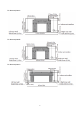
For Mounted plate A, For Mounted plate B, For Mounted plate C, 7
For Mounted plate D, For Mounted plate E, 8
3.2 Outdoor Unit More than 30cm(11.8in) More than 30cm(11.8in) More than 60cm(23.6in) (Service space) Fe n ob ce o sta r cle s More than 60cm(23.6in) More than 70cm(27.6in) Note: The above drawing is only for reference. The appearance of your units may be different. Model W D H W1 A B 770(mm) 300(mm) 555(mm) 823(mm) 530(mm) 290(mm) 30.31(inch) 11.81(inch) 21.85(inch) 32.40 (inch) 20.87(inch) 11.42 (inch) 800(mm) 333(mm) 554(mm) 823(mm) 530(mm) 290(mm) 31.50(inch) 13.
4. Refrigerant Cycle Diagram KSIR009-H117-I, KSIR012-H117-I, KSIR009-H217-I, KSIR012-H217-I, KSIR018-H217-I, KSIR024-H217-I, KSIE009-H121-I, KSIE012-H120-I. INDOOR OUTDOOR CHECK VALVE (Heating Model only) LIQUID SIDE 2-WAY VALVE CAPILIARY TUBE HEAT EXCHANGE (EVAPORATOR) HEAT EXCHANGE (CONDENSER) T1 Room temp. sensor T2 Evaporator temp.
KSIE009-H221-I, KSIE012-H220-I, KSIE018-H220-I, KSIE024-H220-I, KSIR030-H215-I, KSIR036-H215-I. INDOOR OUTDOOR LIQUID SIDE Electronic CAPILIARY TUBE expansion valve CAPILIARY TUBE 2-WAY VALVE HEAT EXCHANGE (EVAPORATOR) T3 Condenser temp. sensor HEAT EXCHANGE (CONDENSER) T4 Ambient temp. sensor T1 Room temp. sensor T2 Evaporator temp. sensor GAS SIDE 3-WAY VALVE 4-WAY VALVE Accumulator Compressor 11 T5 Discharge temp.
5. Wiring Diagram (Pls refer the wiring diagram on the unit) 6.3 Pipe length and the elevation 6 Installation Details Pipe size 6.1 Wrench torque sheet for installation Outside diameter Models 9K torque 1/4in 1500N.cm(153kgf.cm) 1600N.cm(163kgf.cm) Ф9.52mm 3/8in 2500N.cm(255kgf.cm) 2600N.cm(265kgf.cm) 12K,18K 24K,30K,36K Ф12.7mm 1/2in 3500N.cm(357kgf.cm) 3600N.cm(367kgf.cm) Ф15.9mm 5/8in 4500N.cm(459kgf.cm) 4700N.cm(479kgf.cm) 3/8in 1/4in (Ф9.52mm) (Ф6.35mm) 1/2in 1/4in (Ф12.
between indoor and outdoor units must be leak tested and evacuated to remove gas and moisture from the system. Gas leak check (Soap water method): Apply soap water or a liquid neutral detergent on the indoor unit connections or outdoor unit connections by a soft brush to check for leakage of the connecting points of the piping. If bubbles come out, the pipes have leakage. 1.
cylinder, and set the 2-way and 3-way valves to the open position. Be sure to use a hexagonal wrench to operate the valve stems. 7). Mount the valve stems nuts and the service port cap. Be sure to use a torque wrench to tighten the service port cap to a torque 18N·m. Be sure to check the gas leakage. before disconnecting the hose. 7). Mount the valve stem caps and the service port Use torque wrench to tighten the service port cap to a torque of 18N.m. Be sure to check for gas leakage. 6.
unit need to be repaired service port cap to a torque of 18N.m. Be sure to check for gas leakage. 2. Air purging by the refrigerant 1. Evacuation for the whole system Procedure: 1). Confirm that both the 2-way and 3-way valves are set to the opened position. 2). Connect the vacuum pump to 3-way valve’s service port. 3). Evacuation for approximately one hour. Confirm that the compound meter indicates -0.1Mpa(14.5Psi). 4).
up to ensure liquid charge. 2). Purge the air from the charge hose Open the valve at the bottom of the cylinder and press the check valve on the charge set to purge the air (be careful of the liquid refrigerant). 3) Put the charging cylinder onto the electronic scale and record the weight. 4).
7.
8. Electronic Function Dispalys ‘ ’ during self clean operation (if aplicable). 8.1 Abbreviation Dispalys ‘ T1: Indoor room temperature ’ under 8 heating operation (if aplicable). T2: Coil temperature of evaporator When ECO function(optional) is actived,the T3: Coil temperature of condenser T4: Outdoor ambient temperature “ ” illuminates gradually one by one as T5: Compressor discharge temperature In one second interval. 8.2 Display function 8.2.1 Icon explanation on indoor display board.
8.3 Main Protection 8.4 Operation Modes and Functions 8.3.1 Three minutes delay at restart for compressor 1 minute delay for the 1st time stand-up and 3 minutes delay for others. 8.3.2 Temperature protection of compressor top The unit will stop working when the compressor top temp. protector cut off, and will restart after the compressor top temp. protector restart. 8.3.3 Temperature protection of compressor discharge Compressor discharge temp. T5>115℃ for 5s, compressor stops. 8.3.
T4 T3 A+ A TP3+5 B TP3 C D TP3-3 E Setting fan T1-Td ℃(°F) speed D E F G H I L Hold ---TP3 TP3+5 for 5 seconds, the compressor will stop until T3< TP3-3. Actual fan speed A B C M Decrease Resume 8.4.2.
normal heating mode. ----T3 rises to be higher than TCDE1℃. ----T3 keeps to be higher than TCDE2℃ for 80 seconds. ----The machine has run for 15 minutes in defrosting mode. T4 A+ A B C 8.4.3.5 Evaporator coil temperature protection D E T2 8.4.3.3 Indoor fan running rules When the compressor is on, the indoor fan can be set to high/med/low/auto. And the anti-cold wind function has the priority.
8.4.5 Drying mode Indoor fan speed is fixed at breeze and can’t be changed. The louver angle is the same as in cooling mode. All protections are active and the same as that in cooling mode. 8.4.8 Economy function 8.4.8.1 The sleep function is available in cooling, heating or auto mode. 8.4.8.2.
When starting the unit again after shutting down, its louver will restore to the angle originally set by the user, but the precondition is that the angle must be within the allowable range, if it exceeds, it will memorize the maximum angle of the louver. During operation, if the power fails or the end user shuts down the unit in the turbo mode, the louver will restore to the default angle. signal which sent from remote controller every 3 minutes, the buzzer will not respond.
Enquiry information Displaying code Meaning T1 T1 T1 temp. T2 T2 T2 temp. T3 T3 T3 temp. T4 T4 T4 temp. T2B Tb T2B temp. TP TP TP temp. TH TH TH temp. Targeted Frequency FT Targeted Frequency Actual Frequency Fr Actual Frequency Indoor fan speed IF Indoor fan speed Outdoor fan speed OF Outdoor fan speed EXV opening angle LA EXV opening angle Compressor continuous running time CT Compressor continuous running time ST Causes of compressor stop.
F0,F1,…F9 150,151,…159 will display the maximum value or minimum value. Indoor fan 0 OFF speed 1,2,3,4 Low speed, Medium /Outdoor fan speed, High speed, speed Turbo 14-FF For some big capacity motors. Actual fan For some small capacity motors, speed=Display value display value is from 14-FF(hexadecimal), turns to the corresponding fan speed range is from decimal value and then 200-2550RPM. multiply 10. The unit is RPM.
9. Troubleshooting Safety Electricity power is still kept in capacitors even the power supply is shut off. Do not forget to discharge the electricity power in capacitor. Electrolytic Capacitors (HIGH VOLTAGE! CAUTION!) For other models, please connect discharge resistance (approx.100Ω 40W) or soldering iron (plug) between +, terminals of the electrolytic capacitor on the contrary side of the outdoor PCB. Note: The picture above is only for reference. The plug of your side may be different.
9.
9.2 Outdoor unit error display(TBD) 9.3 Diagnosis and Solution 9.3.1 EEPROM parameter error diagnosis and solution(E0/F4) Error Code E0/F4 Malfunction decision Indoor or outdoor PCB main chip does not receive feedback conditions from EEPROM chip. Supposed causes ● Installation mistake ● PCB faulty Trouble shooting: Power off, then restart the unit 2 minutes later. Yes Replace the indoor/outdoor main PCB.
9.3.2 Indoor / outdoor unit’s communication diagnosis and solution(E1) Error Code E1 Malfunction decision Indoor unit does not receive the feedback from outdoor unit during conditions 110 seconds and this condition happens four times continuously.
Remark: Use a multimeter to test the DC voltage between 2 port and 3 port of outdoor unit. The red pin of multimeter connects with 2 port while the black pin is for 3 port. When AC is normal running, the voltage will move alternately between -50V to 50V. If the outdoor unit has malfunction, the voltage will move alternately with positive value. While if the indoor unit has malfunction, the voltage will be a certain value.
9.3.3 Zero crossing detection error diagnosis and solution (E2) Error Code E2 Malfunction decision When PCB does not receive zero crossing signal feedback for 4 conditions minutes or the zero crossing signal time interval is abnormal. Supposed causes ● Connection mistake ● PCB faulty Trouble shooting: Check if the connections and power supply is normal? No Correct the connections. Turn on the unit when the power supply is good. Yes Indoor main PCB is defective. Replace indoor main PCB.
9.3.4 Fan speed has been out of control diagnosis and solution(E3) Error Code E3 Malfunction decision When indoor fan speed keeps too low (300RPM) for certain time, conditions the unit will stop and the LED will display the failure. Supposed causes ● Wiring mistake ● Fan ass’y faulty ● Fan motor faulty ● PCB faulty Trouble shooting: Power off, then restart the unit 2 minutes later No The unit operates normally. No Find out the cause and have it solved No Correct the connections.
Index 1: 1:Indoor or Outdoor DC Fan Motor(control chip is in fan motor) Power on and when the unit is in standby, measure the voltage of pin1-pin3, pin4-pin3 in fan motor connector. If the value of the voltage is not in the range showing in below table, the PCB must has problems and need to be replaced. DC motor voltage input and output(voltage: 220-240V~) NO. Color Signal Voltage 1 Red Vs/Vm 280V~380V 2 --- --- --- 3 Black GND 0V 4 White Vcc 14-17.5V 5 Yellow Vsp 0~5.
9.3.5 Open circuit or short circuit of temperature sensor diagnosis and solution(E5) Error Code E4/E5/F1/F2/F3 Malfunction decision If the sampling voltage is lower than 0.06V or higher than 4.94V, conditions the LED will display the failure. Supposed causes ● Wiring mistake ● Sensor faulty ● PCB faulty Trouble shooting: Check the connection between temperature sensor and PCB.
9.3.6 Refrigerant Leakage Detection diagnosis and solution(EC) Error Code EC Malfunction decision Define the evaporator coil temp.T2 of the compressor just starts conditions running as Tcool. In the beginning 5 minutes after the compressor starts up, if T2 <Tcool-2°C(Tcool-35.6°F) does not keep continuous 4 seconds and this situation happens 3 times, the display area will show “EC” and AC will turn off.
9.3.6 Overload current protection diagnosis and solution(F0) Error Code F0 Malfunction decision An abnormal current rise is detected by checking the specified conditions current detection circuit. Supposed causes ● Power supply problems. ● System blockage ● PCB faulty ● Wiring mistake ● Compressor malfunction Check the power supply No Stop the unit No Clear the blockage No Replace the compressor No Correct the connections or replace the wires.
9.3.7 IPM malfunction or IGBT over-strong current protection diagnosis and solution(P0) Error Code P0 Malfunction decision When the voltage signal that IPM send to compressor drive chip conditions is abnormal, the display LED will show “P0” and AC will turn off.
For example: Note: The photos below are only for reference, it’s may be not same totally with the ones on your side.
P-W N-U 39
N-V N-W 40
9.3.8 Over voltage or too low voltage protection diagnosis and solution(P1) Error Code P1 Malfunction decision An abnormal voltage rise or drop is detected by checking the conditions specified voltage detection circuit. Supposed causes ● Power supply problems. ● System leakage or block ● PCB faulty Trouble shooting: Check the power supply No Stop the unit No Correct the connections or replace the wires.
9.3.9 High temperature protection of compressor top diagnosis and solution(P2) Error Code P2 Malfunction decision If the sampling voltage is not 5V, the LED will display the failure. conditions Supposed causes ● Power supply problems. ● System leakage or block ● PCB faulty Trouble shooting: Check the air flow system of indoor and outdoor units Yes Clear up the air inlet and outlet or the heat exchanger of indoor and outdoor units.
9.3.10 Inverter compressor drive error diagnosis and solution(P4) Error Code P4 Malfunction decision An abnormal inverter compressor drive is detected by a special conditions detection circuit, including communication signal detection, voltage detection, compressor rotation speed signal detection and so on.
Main parts check 1. Temperature sensor checking Disconnect the temperature sensor from PCB, measure the resistance value with a tester. Temperature sensors. Room temp.(T1) sensor, Indoor coil temp.(T2) sensor, Outdoor coil temp.(T3) sensor, Outdoor ambient temp.(T4) sensor, Compressor discharge temp.(T5) sensor. Measure the resistance value of each winding by using the multi-meter.
Appendix 1 Temperature Sensor Resistance Value Table for T1,T2,T3,T4 (°C--K) °C °F K Ohm °C °F K Ohm °C °F K Ohm °C °F K Ohm -20 -4 115.266 20 68 12.6431 60 140 2.35774 100 212 0.62973 -19 -2 108.146 21 70 12.0561 61 142 2.27249 101 214 0.61148 -18 0 101.517 22 72 11.5 62 144 2.19073 102 216 0.59386 -17 1 96.3423 23 73 10.9731 63 145 2.11241 103 217 0.57683 -16 3 89.5865 24 75 10.4736 64 147 2.03732 104 219 0.56038 -15 5 84.
Appendix 2 Temperature Sensor Resistance Value Table for T5 (°C --K) °C °F K Ohm °C °F K Ohm °C °F K Ohm °C °F K Ohm -20 -4 542.7 20 68 68.66 60 140 13.59 100 212 3.702 -19 -2 511.9 21 70 65.62 61 142 13.11 101 214 3.595 -18 0 483 22 72 62.73 62 144 12.65 102 216 3.492 -17 1 455.9 23 73 59.98 63 145 12.21 103 217 3.392 -16 3 430.5 24 75 57.37 64 147 11.79 104 219 3.296 -15 5 406.7 25 77 54.89 65 149 11.38 105 221 3.
Appendix 3: 9ΔT(℃) ΔT(℉) = 5 °C °F °C °F °C °F °C °F °C °F -5 23 21 69.8 51 123.8 82 179.6 113 235.4 -4 24.8 22 71.6 52 125.6 83 181.4 114 237.2 -3 26.6 23 73.4 53 127.4 84 183.2 115 239 -2 28.4 24 75.2 54 129.2 85 185 116 240.8 -1 30.2 25 77 55 131 86 186.8 117 242.6 0 32 25.5 77.9 56 132.8 87 188.6 118 244.4 0.5 32.9 26 78.8 57 134.6 88 190.4 119 246.2 1 33.8 27 80.6 58 136.4 89 192.2 120 248 1.5 34.7 28 82.
2.Compressor checking Measure the resistance value of each winding by using the tester. Position Resistance Value ASN98D22UFZ ASM135D23UFZ ATF235D22UMT 1.75 Ω 0.75 Ω ATF250D22UMT Blue - Red Blue - Black Red - Blue 1.57Ω 48 0.
3. IPM continuity check Turn off the power, let the large capacity electrolytic capacitors discharge completely, and dismount the IPM. Use a digital tester to measure the resistance between P and UVWN; UVW and N. Digital tester (+)Red Normal resistance value Digital tester (-)Black (+)Red N V (Several MΩ) V (-)Black U ∞ U P Normal resistance value W W ∞ N (Several MΩ) (+)Red 4: Indoor outdoor Fan Motor Measure the resistance value of each winding by using the tester.
5: Pressure On Service Port Cooling chart: °F(°C) ODT IDT 75 85 95 105 115 (23.89) (29.44) (35) (40.56) (46.11) BAR 70/59 8.2 7.8 8.1 8.6 10.1 BAR 75/63 8.6 8.3 8.7 9.1 10.7 BAR 80/67 9.3 8.9 9.1 9.6 11.2 75 85 95 105 115 (23.89) (29.44) (35) (40.56) (46.11) °F(°C) ODT IDT PSI 70/59 119 113 117 125 147 PSI 75/63 124 120 126 132 155 PSI 80/67 135 129 132 140 162 75 85 95 105 115 (23.89) (29.44) (35) (40.56) (46.
Heating Chart: ODT °F (°C) IDT 57/53 47/43 37/33 27/23 17/13 (13.89/11.67) (8.33/6.11) (2.78/0.56) (-2.78/-5) (-8.33/-10.56) BAR 55 30.3 28.5 25.3 22.8 20.8 BAR 65 32.5 30.0 26.6 25.4 23.3 BAR 75 33.8 31.5 27.8 26.3 24.9 57/53 47/43 37/33 27/23 17/13 (13.89/11.67) (8.33/6.11) (2.78/0.56) (-2.78/-5) (-8.33/-10.
The Klimaire logo is a registered Trademark of Klimaire Products Inc. Copyright 2016 Klimaire Products Inc. 2190 NW 89 Place, Doral, FL 33172 - USA Tel: (305)593-8358 Fax (305) 675-2212 www.klimaire.com sales@klimaire.com The design and specifications are subject to change without prior notice for product improvement. Consult with the sales agency or manufacturer for details.