
User Manual


5
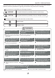
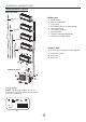
Identification of parts
OPERATING INSTRUCTIONS
Indoor unit
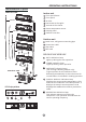
Outdoor unit
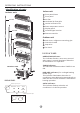
Indoor unit
IMPORTANT:
For multi-split type air conditioner, one outdoor
unit can match different types of indoor units.
So all the pictures in this manual are for explan-
ation purpose only. Your air conditioner may be
slightly different. The actual shape shall prevail.
The following pages introduce several kinds of
indoor units matching with the outdoor units.
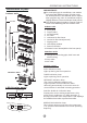
LED Display panel
AUTO indication lamp
Lights up during the Auto operation.
OPERATION indication lamp
This indicator appears only when the compressor
is in operation and indicates the current operating
frequency.
TIMER indication lamp
Lights up during Timer operation.
DEFROST indication lamp
(For Cooling & Heating models only):
Lights up when the air conditioner starts
defrosting automatically or when the warm air
control feature is activated in heating operation.
1. Front panel
2. Top air intake
3. Air filter(Inside)
4. Air outlet
5.
6.
7. Display panel
8. LED display window
9. Remote controller
10. Manual control button(Behind the front panel)
Horizontal air flow louver
Vertical air flow louver(Internal)
11. Refrigerant connecting pipe, drain hose and
electric wiring
12. Stop valve
13. Air outlet
DIGITAL DISPLAY indication lamp
Displays the current setting temperature. Only
when the air conditioner is in FAN operation, it
displays the actual room temperature. And d
.
isplays
the malfunction code or protection code.
Display panel
Signal receptor
AUTO
DEFROST
OPERATION
TIMER
Signal receptor
AUTO TIMER
DEF.
FREQUENCY
(1)
(2)
Outdoor unit
One-twin
One-three
One-four
One-five
9
11
12
13
4
3
5
2
6
1
10
7
8