SPLIT-TYPE ROOM AIR CONDITIONER Installation Manual KSIF Series All Model Numbers IMPORTANT NOTE: Read this manual carefully before installing or operating your new air conditioning unit. Make sure to save this manual for future reference.
Table of Contents Installation Manual 0 Safety Precautions ................................... 4 1 Accessories .................................................. 6 2 Installation Summary - Indoor Unit 3 Unit Parts ....... 8 .................................................. 10 4 Indoor Unit Installation ......... 11 1. Select installation location ......................... 2. Attach mounting plate to wall ................ 3. Drill wall hole for connective piping ...... 4. Prepare refrigerant piping .
6 Refrigerant Piping Connection ........ 25 A. Note on Pipe Length ............................................................. B. Connection Instructions –Refrigerant Piping ............... 1. Cut pipe ............................................................................... 2. Remove burrs ..................................................................... 3. Flare pipe ends ................................................................. 4. Connect pipes ......................................
Safety Precautions Read Safety Precautions Before Installation Incorrect installation due to ignoring instructions can cause serious damage or injury. The seriousness of potential damage or injuries is classified as either a WARNING or CAUTION. This symbol indicates that ignoring instructions may cause death or serious injury. WARNING This symbol indicates that ignoring instructions may cause moderate injury to your person, or damage to your unit or other property.
WARNING 6. For all electrical work, follow all local and national wiring standards, regulations, and the Installation Manual. You must use an independent circuit and single outlet to supply power. Do not connect other appliances to the same outlet. Insufficient electrical capacity or defects in electrical work can cause electrical shock or fire. 7. For all electrical work, use the specified cables. Connect cables tightly, and clamp them securely to prevent external forces from damaging the terminal.
1 Accessories The air conditioning system comes with the following accessories. Use all of the installation parts and accessories to install the air conditioner. Improper installation may result in water leakage, electrical shock and fire, or cause the equipment to fail. Name Shape Quantity Mounting plate 1 Clip anchor 5 Mounting plate fixing screw ST3.9 X 25 5 Remote controller 1 Fixing screw for remote controller holder ST2.
Shape Name Quantity INVERTER SPLIT-TYPE ROOM AIR CONDITIONER Owner’s Manual KSIF Series All Model Numbers 1 Owner’s manual IMPORTANT NOTE: Read this manual carefully before installing or operating your new air conditioning unit. Make sure to save this manual for future reference.
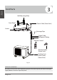
Installation Overview 2 Installation Summary - Indoor Unit 1 2 15cm (5.9in) 12cm (4.75in) 12cm (4.75in) 2.3m (90.
6 7 1 Connect Piping (Page 25) Installation Overview 5 2 3 Connect Wiring (Page 17) Prepare Drain Hose (Page 14) 8 Wrap Piping and Cable (Page 18) 9 STEP 8 Mount Indoor Unit (Page 18) Page 9
3 Unit Parts Installation Overview Wall Mounting Plate Front Panel Power Cable (Some Units) Louver Drainage Pipe Signal Cable Refrigerant Piping Remote Control Remote Holder (Some Units) Outdoor Unit Power Cable (Some Units) Fig. 2.1 NOTE ON ILLUSTRATIONS Illustrations in this manual are for explanatory purposes. The actual shape of your indoor unit may be slightly different. The actual shape shall prevail.
4 Indoor Unit Installation Indoor Unit Installation Installation Instructions – Indoor Unit PRIOR TO INSTALLATION Before installing the indoor unit, refer to the label on the product box to make sure that the model number of the indoor unit matches the model number of the outdoor unit.
Refer to the following diagram to ensure proper distance from walls and ceiling: 5.9in (15cm) or more Indoor Unit Installation 4.75in (12cm) or more 4.75in (12cm) or more 90.55in (2.3m) or more Fig. 3.1 Step 2: Attach mounting plate to wall Step 3: Drill wall hole for connective piping The mounting plate is the device on which you will mount the indoor unit.
W all Outdoor 39mm (1.5in) 39mm (1.5in) 47.1mm (1.85in) 285mm (11.2in) Indoor unit outline Left rear wall hole 65mm (2.5in) 115.6mm(4.55in) 117.5mm(4.62in) 45mm(1.7in) 101.6mm(4in) Right rear wall hole 65mm (2.5in) Indoor Unit Installation Fig. 3.2 Fig.3.2 398mm(15.67in) 233.1mm(9.17in) 146.5mm(5.76in) 47.1mm (1.85in) 5-7m m (0.2-0.3in) Indoor 715mm(28in) Model A • Relative distances between screw holes Correct orientation of Mounting Plate 39mm (1.5in) 47.1mm (1.85in) 439mm(17.
Step 4: Prepare refrigerant piping The refrigerant piping is inside an insulating sleeve attached to the back of the unit. You must prepare the piping before passing it through the hole in the wall. Refer to the Refrigerant Piping Connection section of this manual for detailed instructions on pipe flaring and flare torque requirements, technique, etc. Indoor Unit Installation 1. Based on the position of the wall hole relative to the mounting plate, choose the side from which the piping will exit the unit.
Step 5: Connect drain hose PLUG THE UNUSED DRAIN HOLE By default, the drain hose is attached to the lefthand side of unit (when you’re facing the back of the unit). However, it can also be attached to the right-hand side. To prevent unwanted leaks you must plug the unused drain hole with the rubber plug provided. 1. To ensure proper drainage, attach the drain hose on the same side that your refrigerant piping exits the unit. CORRECT 2.
BEFORE PERFORMING ELECTRICAL WORK, READ THESE REGULATIONS 1. All wiring must comply with local and national electrical codes, and must be installed by a licensed electrician. 2. All electrical connections must be made according to the Electrical Connection Diagram located on the panels of the indoor and outdoor units. 3. If there is a serious safety issue with the power supply, stop work immediately.
Step 6: Connect signal cable TAKE NOTE OF FUSE SPECIFICATIONS The signal cable enables communication between the indoor and outdoor units. You must first choose the right cable size before preparing it for connection. The air conditioner’s circuit board (PCB) is designed with a fuse to provide overcurrent protection. The specifications of the fuse are printed on the circuit board, such as: T3.15A/250VAC, T5A/250VAC, etc.
6. Feed the signal wire through this slot, from the back of the unit to the front. DO NOT INTERTWINE SIGNAL CABLE WITH OTHER WIRES 7. Facing the front of the unit, match the wire colors with the labels on the terminal block, connect the u-lug and and firmly screw each wire to its corresp onding terminal. While bundling these items together, do not intertwine or cross the signal cable with any other wiring.
If refrigerant piping is already embedded in the wall, do the following: 1. Hook the top of the indoor unit on the upper hook of the mounting plate. 2. Use a bracket or wedge to prop up the unit, giving you enough room to connect the refrigerant piping, signal cable, and drain hose. Refer to Fig. 3.13 for an example. 3. Connect drain hose and refrigerant piping (refer to Refrigerant Piping Connection section of this manual for instructions). 4.
5 Outdoor Unit Installation 24in (60cm) above Outdoor Unit Installation Installation Instructions – Outdoor Unit Step 1: Select installation location Before installing the outdoor unit, you must choose an appropriate location. The following are standards that will help you choose an appropriate location for the unit. 12in (30c on le m) ft Proper installation locations meet the following standards: Meets all spatial requirements shown in Installation Space Requirements ( Fig. 4.
SPECIAL CONSIDERATIONS FOR EXTREME WEATHER If the drain joint comes with a rubber seal (see Fig. 4.4 - A ), do the following: If the unit is exposed to heavy wind: 1. Fit the rubber seal on the end of the drain joint that will connect to the outdoor unit. Install unit so that air outlet fan is at a 90° angle to the direction of the wind. If needed, build a barrier in front of the unit to protect it from extremely heavy winds. See Fig. 4.2 and Fig. 4.3 below. Strong wind 2.
Step 3: Anchor outdoor unit The outdoor unit can be anchored to the ground or to a wall-mounted bracket. W A UNIT MOUNTING DIMENSIONS B Air inlet D Outdoor Unit Dimensions W Air outlet A Fig. 4.5 Mounting Dimensions Air inlet Distance A 26.8”x17”x11.2” (681x434x285mm) 18.10” (460mm) 27.5”x21.6”x10.62” (700x550x270mm) 17.7” (450mm) 10.24” (260mm) 30.7”x21.25”x9.85” (780x540x250mm) 21.6” (549mm) 10.85” (276mm) 33.25”x27.5”x12.6” (845x700x320mm) 22” (560mm) 3.2” (335mm1) 31.9”x22”x12.
If you will install the unit on a wall-mounted bracket , do the following: CAUTION Before installing a wall-mounted unit, make sure that the wall is made of solid brick, concrete, or of similarly strong material. The wall must be able to support at least four times the weight of the unit. 1. Mark the position of bracket holes based on dimensions in the Unit Mounting Dimensions chart. 2. Pre-drill the holes for the expansion bolts. 1.
PA Y ATTENTION TO LIVE WIRE WARNING BEFORE PERFORMING ANY ELECTRICAL OR WIRING WORK, TURN OFF THE MAIN POWER TO THE SYSTEM. WARNING 1. Prepare the cable for connection: USE THE RIGHT CABLE • Indoor Power Cable (if applicable): H05VV-F or H05V2V2-F • Outdoor Power Cable: H07RN-F • Signal Cable: H07RN-F ALL WIRING MUST PERFORMED STRICTLY IN ACCORDANCE WITH THE WIRING DIRGRAM LOCATED INSIDE THE OUTDOOR UNIT S’ WIRE COVER. 2. Unscrew the electrical wiring cover and remove it.
6 Refrigerant Piping Connection The length of refrigerant piping will affect the performance and energy efficiency of the unit. Nominal efficiency is tested on units with a pipe length of 5 meters (16.5ft). Refer to the table below for specifications on the maximum length and drop height of piping.
DO NOT DEFORM PIPE WHILE CUTTING Flare nut Be extra careful not to damage, dent, or deform the pipe while cutting. This will drastically reduce the heating efficiency of the unit. Copper pipe Step 2: Remove burrs Burrs can affect the air-tight seal of refrigerant piping connection. They must be completely removed. Fig. 5.3 1. Hold the pipe at a downward angle to prevent burrs from falling into the pipe. 4. Remove PVC tape from ends of pipe when ready to perform flaring work. 2.
6. Place flaring tool onto the form. 7. Turn the handle of the flaring tool clockwise until the pipe is fully flared. 8. Remove the flaring tool and flare form, then inspect the end of the pipe for cracks and even flaring. Instructions for Connecting Piping to Indoor Unit 1. Align the center of the two pipes that you will connect. See Fig. 5.7 . Step 4: Connect pipes When connecting refrigerant pipes, be careful not to use excessive torque or to deform the piping in any way.
Instructions for Connecting Piping to Outdoor Unit 1. Unscrew the cover from the packed valve on the side of the outdoor unit. (See Fig. 5.9 ) USE SPANNE R TO GRIP MAIN BOD Y OF VALVE Torque from tightening the flare nut can snap off other parts of valve. Valve cover Fig. 5.9 2. Remove protective caps from ends of valves. 3. Align flared pipe end with each valve, and tighten the flare nut as tightly as possible by hand. 4. Using a spanner, grip the body of the valve.
7 Air Evacuation MC Preparations and Precautions Air and foreign matter in the refrigerant circuit can cause abnormal rises in pressure, which can damage the air conditioner, reduce its efficiency, and cause injury. Use a vacuum pump and manifold gauge to evacuate the refrigerant circuit, removing any non-condensable gas and moisture from the system.
3. Open the Low Pressure side of the manifold gauge. Keep the High Pressure side closed. 4. Turn on the vacuum pump to evacuate the system. 5. Run the vacuum for at least 15 minutes, or until the Compound Meter reads -76cmHG (-10 5Pa). 6. Close the Low Pressure side of the manifold gauge, and turn off the vacuum pump. Flare nut Cap 7. Wait for 5 minutes, then check that there has been no change in system pressure. 8.
Electrical and Gas Leak Checks Electrical Safety Checks After installation, confirm that all electrical wiring is installed in accordance with local and national regulations, and according to the Installation Manual. 8 WARNING – RISK OF ELECTRIC SHOCK ALL WIRING MUST COMPLY WITH LOCAL AND NATIONAL ELECTRICAL CODES, AND MUST BE INSTALLED BY A LICENSED ELECTRICIAN. BEFORE TEST RUN Check Grounding Work Measure grounding resistance by visual detection and with grounding resistance tester.
9 Test Run Before Test Run Only perform test run after you have completed the following steps: • • • Electrical Safety Checks – Confirm that the unit’s electrical system is safe and operating properly Gas Leak Checks – Check all flare nut connections and confirm that the system is not leaking Confirm that gas and liquid (high and low pressure) valves are fully open Test Run Instructions You should perform the Test Run for at least 30 minutes. 1. Connect power to the unit. 2.
DOUBLE-CHECK PIPE CONNECTIONS During operation, the pressure of the refrigerant circuit will increase. This may reveal leaks that were not present during your initial leak check. Take time during the Test Run to double-check that all refrigerant pipe connection points do not have leaks. Refer to Gas Leak Check section for instructions. Manual control button 5. After the Test Run is successfully complete, and you confirm that all checks points in List of Checks to Perform have PASSED, do the following: a.
2190 NW 89 Place, Doral, FL 33172 - USA Tel: (305) 594 - 4972 www.klimaire.com Fax (305) 675-2212 sales@klimaire.com The Klimaire logo is a registered Trademark of Klimaire Products inc. Copyright 2016 Klimaire Products Inc. The design and specifications are subject to change without prior notice for product improvement. Consult with the sales agency or manufacturer for details.