
Installation manual


Page 24
WARNING
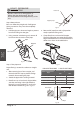
1. Prepare the cable for connection:
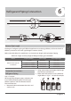
USE THE RIGHT CABLE
• Indoor Power Cable (if applicable): H05VV-F
or H05V2V2-F
• Outdoor Power Cable: H07RN-F
• Signal Cable: H07RN-F
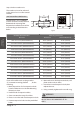
Minimum Cross-Sectional Area of
Power and Signal Cables
Other Regions
Rated Current of
Appliance (A)
Nominal Cross-
Sectional Area (mm²)
> 3 and ≤ 6 0.75
> 6 and ≤ 10 1
> 10 and ≤ 16 1.5
> 16 and ≤ 25 2.5
> 25 and ≤ 32 4
> 32 and ≤ 40 6
a. Using wire strippers, strip the rubber
jacket from both ends of cable to reveal
about 40mm (1.57in) of the wires inside.
b. Strip the insulation from the ends of the
wires.
c. Using a wire crimper, crimp u-lugs on the
ends of the wires.
PA Y ATTENTION TO LIVE WIRE
While crimping wires, make sure you clearly
distinguish the Live (“L”) Wire from other wires.
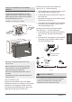
2. Unscrew the electrical wiring cover and
remove it.
3. Unscrew the cable clamp below the terminal
block and place it to the side.
4. Match the wire colors/labels with the labels on
the terminal block, and firmly screw the u-lug
of each wire to its corresponding terminal.
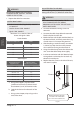
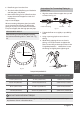
5. After checking to make sure every connection
is secure, loop the wires around to prevent
rain water from flowing into the terminal.
6. Using the cable clamp, fasten the cable to the
unit. Screw the cable clamp down tightly.
7. Insulate unused wires with PVC electrical tape.
Arrange them so that they do not touch any
electrical or metal parts.
8. Replace the wire cover on the side of the unit,
and screw it in place.
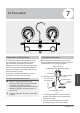
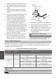
Outdoor Unit
Installation
Cover
Outdoor Unit Wiring Diagram
is located on the inside of the
wire cover on the outdoor unit.
Fig. 4.6
BEFORE PERFORMING ANY ELECTRICAL
OR WIRING WORK, TURN OFF THE MAIN
POWER TO THE SYSTEM.
WARNING
ALL WIRING MUST PERFORMED STRICTLY
IN ACCORDANCE WITH THE WIRING
DIRGRAM LOCATED INSIDE THE OUTDOOR
UNIT S WIRE COVER.
’
North America
Appliance Amps (A)
AWG
10 18
13 16
18 14
25 12
30 10