
Installation Manual


Page 10
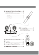
Unit Parts
3
Installation
Overview
NOTE ON ILLUSTRATIONS
Illustrations in this manual are for explanatory purposes. The actual shape of your indoor
unit may be slightly different. The actual shape shall prevail.
Fig. 2.1
NOTE: The installation must be performed in accordance with the requirement of local and
national standards. The installation may be slightly different in different areas.
Wall Mounting Plate
Power Cable (Some Units)
Refrigerant Piping
Signal Cable
Remote Controller
Drainage Pipe
Louver
Remote controller Holder
(Some Units)
Functional Filter (On Front of
Main Filter - Some Units)
Front Panel
Outdoor Unit Power Cable
(Some Units)
1
2
3
4
5
6
7
8
9
10
11
(1) (2)
1
2
3
4
6
7
8
9
10
11
Air-break switch
3
1
2
4
5
6
7
8
11
5