
Service Manual
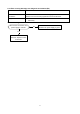
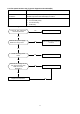
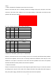
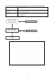
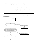
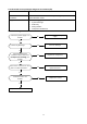
Table Of Contents

33
Index 1:
1: Indoor or Outdoor DC Fan Motor (control chip is in fan motor)
Power on and when the unit is in standby, measure the voltage of pin1-pin3, pin4-pin3 in fan motor
connector. If the value of the voltage is not in the range showing in below table, the PCB must has
problems and need to be replaced.
DC motor voltage input and output (voltage: 220-240V~)
NO.
Color
Signal
Voltage
1
Red
Vs/Vm
280V~380V
2
---
---
---
3
Black
GND
0V
4
White
Vcc
14-17.5V
5
Yellow
Vsp
0~5.6V
6
Blue
FG
14-17.5V
DC motor voltage input and output(voltage :115V~)
NO.
Color
Signal
Voltage
1
Red
Vs/Vm
140V~190V
2
---
---
---
3
Black
GND
0V
4
White
Vcc
14-17.5V
5
Yellow
Vsp
0~5.6V
6
Blue
FG
14-17.5V
2. Outdoor DC Fan Motor (control chip is in outdoor PCB)
Power on, and check if the fan can run normally, if the fan can run normally, the PCB must have problems
and need to be replaced, If the fan can’t run normally, measure the resistance of each two pins. If the
resistance is not equal to each other, the fan motor must have problems and need to be replaced,
otherwise the PCB must have problems and need to be replaced.
3. Indoor AC Fan Motor
Power on and set the unit running in fan mode at high fan speed. After running for 15 seconds, measure
the voltage of pin1 and pin2. If the value of the voltage is less than 100V (208~240V power supply) or
50V (115V power supply), the PCB must have problems and need to be replaced.