. KLIMAIRE 60Hz PTAC WINDOW Top air discharge. KTHM SERIES . .
CONTENTS 1. Precaution ........................................................................................................................................... 1 1.1 Safety Precaution. ............................................................................................................................. 1 1.2 Warning .............................................................................................................................................. 1 2.
1. Precaution 1.1 Safety Precaution. To prevent injury to the user or other people and property damage, the following instructions must be followed. Incorrect operation due to ignoring instruction will cause harm or damage. Before service unit, be sure to read this service manual at first. 1.2 Warning Installation Do not use a defective or underrated circuit breaker. Use this appliance on a dedicated circuit. There is risk of fire or electric shock.
Do not install the product on a defective installation stand. It may cause injury, accident, or damage to the product. Be sure the installation area does not deteriorate with age. If the base collapses, the air conditioner could fall with it, causing property damage, product failure, and personal injury. Do not let the air conditioner run for a long time when the humidity is very high and a door or a window is left open. Moisture may condense and wet or damage furniture.
There is risk of property damage, failure of product, or electric shock. Do not open the inlet grill of the product during operation. (Do not touch the electrostatic filter, if the unit is so equipped.) There is risk of physical injury, electric shock, or product failure. When the product is soaked (flooded or submerged), contact an Authorized service center. There is risk of fire or electric shock. Be caution that water could not enter the product.
could cause product malfunction or inefficient operation. Operational. Do not expose the skin directly to cool air for long periods of time. (Do not sit in the draft). This could harm to your health. Do not use the product for special purposes, such as preserving foods, works of art, etc. It is a consumer air conditioner, not a precision refrigerant system There is risk of damage or loss of property. Do not block the inlet or outlet of air flow. It may cause product failure.
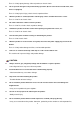
2. Function and control panel. 202021890236 KTHM009-E3C2 KTHM012-E3C2 KTHM015-E5C2 KTHM009-E3H2 KTHM012-E3H2 KTHM015-E5C2 The controls featured in this manual are representative of many available models. Your model may offer slightly different features. POWER - Press the POWER button to turn the unit on or off. When the unit is on, the power indicator light will be green.When the unit is off, the light will go out. MODE - Push this button to cycle through the modes from COOL-HEAT-FAN-COOL.
- FAN:Fan operation only without heating and cooling. UP/DOWN BUTTONS ( / ) - Push the UP (or DOWN) button to increase (or decrease) the set temperature of the unit in cooling or heating mode.The temperature can be set by increments of 1℃ (1℉).The setting temperature appears in the display. NOTE:Press and hold and buttons together for 3 seconds will alternate the temperature display between ℃ & ℉ scale.
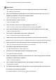
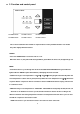
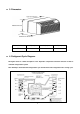
3. Dimension. Dimension Mode W(mm) H(mm) D(mm) PTAC 1067 408 606 4. Refrigerant Cycle Diagram. The figure below is a brief description of the important components and their function in what is called the refrigeration system. This will help to understand the refrigeration cycle and the flow of the refrigerant in the cooling cycle.
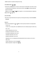
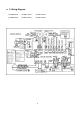
5. Wiring Diagram.
6 Electronic function 6.1 Terms and definitions T1: Temperature of indoor ambient (TA) T2: Temperature of evaporator (TC). T3: Temperature of condenser (TE) T4: Temperature of outdoor ambient (T0) TS: The set temperature. DAHT: Temperature of discharge (T5) DAHT: Temperature of discharge (T6) 6.2 Electric Control working environment Input voltage: 187~264V for 50Hz models and 97~127V for 60Hz models; 208~230V or 238~291V for 60Hz models 6.3 Protection function 6.3.
T4 Operate on high speed T01 T02 Operate on low speed When T4﹥T01 and lasts for 1 minute, the fan motor will operates at high speed. When T4﹤T02 and lasts for 1 minute, the fan motor will operates at low speed. When T02≤T4≤T01: A) If fan motor is off originally, it will operate at high speed. B) If fan motor is on originally, it will keep on working at the original speed. 6.4.3.
TE7 TE8 TE15 Compressor Fan motor Fan motor (low speed) Compressor on Fan motor on (High/low speed is determined by T4) Compressor Fan motor Compressor on Fan motor on (High/low speed is determined by T4) TE9 If T2﹥TE7, this unit turns into the protection of compressor off , and quits this protection when T2≤TE9. If T2﹥TE8,it turns into the protection of fan motor off , and quits this protection when T2≤TE9.
Operation conditon for heater or compressor Heater(compressor) off (T1-Ts)℉ 2 -2 Heater(compressor) on 6.5.2.1 The Electric heater operates as below: a. When T1﹤Ts-2℉, the fan motor operates, and 3 seconds later, the heater is on and operates at low speed within 30 seconds. After 30 seconds, it will change to the setting speed. If the DAHT temperature checked is higher than the protection temperature, when the heater operating, the fan motor will be off automatically. b.
7 Installation details 7.1 How to install the unit CAUTION: There are sharp edges that can cause serious cuts. When lifting the air conditioner, it is HEAVY. Use 2 people to lift.
- For existing sleeve, you should measure the wall sleeve dimensions. - Install the new air conditioner according to these installation instructions to achieve the best performance. All wall sleeves used to mount the new air conditioner must be in good structural condition and have a rear grille that securely attaches to the sleeve or the flange of the sleeve to secure the new air conditioner. - To avoid vibration and noise, make sure the unit is installed securely and firmly.
- Rotate the vent control lever to either open or close the vent door.(See Fig.6) NOTE: When vent control lever set at CLOSE, only the air inside the room is circulated and filtered. When set at OPEN, some outdoor air will be drawn into room. This will reduce heating or cooling efficiency. - Lift unit level and slide unit into wall sleeve until firmly against front of wall sleeve and secure with 4 screws and washers (supplied) through the unit flange holes. (See Fig.7 and Fig.8) - Reinstall front panel.
7.2 Care and cleaning FRONT PANEL AND CARE - Turn unit off and disconnect power supply. To clean, use water and a mild detergent. DO NOT use bleach and abrasive. Some commercial cleaners may damage the plastic parts. OUTDOOR COIL - Coil on outdoor side of unit should be checked regularly. Unit will need to be removed to inspect dirt build-up that will occur on the inside of the coil. If clogged with dirt and soot, coil should be professionally cleaned.
Prevent clogged indoor coil. Reduce risk of premature component failure. - To Clean Air Filters: Vacuum off heavy soil. Run water through filter. Dry thoroughly before replacing. - Removing Air Filter (See.Fig.10) - Replacing Air Filter (See.Fig.11) VENT DOOR FILTER IMPORTANT:TURN UNIT OFF BEFORE CLEANING. - Make sure to remove the shipping screw from the vent door.(See.Fig.5) - Rotate the vent control lever to open the vent door. (See. Fig.6) - Remove four screws from the vent door filter. (See.Fig.
8 Operation characteristics 8.1 Cooling operation. Outdoor air temp.℃ DB Indoor air temp. ℃ DB 8.2 Characteristic of temperature sensor. Temp.℃ Resistance KΩ Temp.℃ Resistance KΩ Temp.℃ Resistance KΩ -10 62.2756 17 14.6181 44 4.3874 -9 58.7079 18 13.918 45 4.2126 -8 56.3694 19 13.2631 46 4.0459 -7 52.2438 20 12.6431 47 3.8867 -6 49.3161 21 12.0561 48 3.7348 -5 46.5725 22 11.5 49 3.5896 -4 44 23 10.9731 50 3.451 -3 41.5878 24 10.4736 51 3.
2 31.5635 29 8.3357 56 2.7382 3 29.9058 30 7.9708 57 2.6368 4 28.3459 31 7.6241 58 2.5397 5 26.8778 32 7.2946 59 2.4468 6 25.4954 33 6.9814 60 2.3577 7 24.1932 34 6.6835 61 2.2725 8 22.5662 35 6.4002 62 2.1907 9 21.8094 36 6.1306 63 2.1124 10 20.7184 37 5.8736 64 2.0373 11 19.6891 38 5.6296 65 1.9653 12 18.7177 39 5.3969 66 1.8963 13 17.8005 40 5.1752 67 1.830 14 16.9341 41 4.9639 68 1.7665 15 16.1156 42 4.7625 69 1.
UNIT NOT COOLING/HEATING ROOM Make sure that curtains, blinds or furniture are not restricting Unit air discharge section is blocked Temperature setting is not high or low Reset to a lower or higher temperature setting. enough. Remove and clean filters. Note: Set point limits may not allow Allow sufficient amount of time for unit to heat or cool the room. or blocking unit airflow.
The Klimaire logo is a registered Trademark of Klimaire Products inc. Copyright 2010 Klimaire Products Inc.