
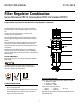
Product Manual

3
WHERE TO INSTALL A FILTER &
REGULATOR COMBINATION?
• Install as far away from compressor as possible. This allows
air to cool and moisture to condense. It is easier to remove
condensed moisture than vapours.
• As close to tool/equipment as possible.
• It must be installed before Lubricator or else it will filter out
the oil in the air coming from the Lubricator.
• With arrows pointing in the direction of air flow (towards tool/
equipment).
1. Install in clean/ acid free atmosphere.
2. Flush the piping for dirt, dust and other foreign particles.
3. Connect the supply pressure to IN port and take the outlet
from the OUT port. (If the unit is installed in reverse direction
the air will continuously flow through the bonnet and the
setting of the pressure will not be possible).
4. Use proper thread sealant for taper threads to have a leak
proof connection.
5. Set the pressure in the regulator within the specified Limit.
Otherwise the spring may break.
6. Open the inlet valve/ switch on the air supply.
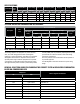
7. When using (G) parallel thread nipples, check the length of the
thread from the given table.
INSTALLATION INSTRUCTIONS
Pressure Gauge must be installed on the pressure gauge port on
the Filter & Regulator Combination. Filter & Regulator Combination
has 1/8” pressure gauge port. The Pressure gauge must also be of
1/8” port size. Steps to install the pressure gauge:
1. Unscrew the bolt on the pressure gauge port.
2. Replace the bolt with the corresponding size Pressure Gauge.
3. Pressure Gauge can be installed on any of the two Pressure
Gauge ports on Filter & Regulator combination.
NOTE: Pressure Gauge may not be included as a standard
accessory, but can be purchased separately.
WHERE TO INSTALL A PRESSURE GAUGE?
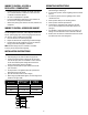
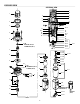
1. To set the regulator, pull the regulating knob till “Red Band”
(Indicator Ring) is visible (Fig.1).
2. To increase the pressure, turn the regulating knob in clockwise
direction.
3. To reduce the pressure, turn the regulating knob in counter
clockwise direction.
4. Set the pressure always in the ascending manner.
5. Set the pressure within the specified Limit.
6. For draining the condensate water collected in the Bowl
(21.1.1). Press and hold the knob of the Drain valve (21.2)
(see Fig.3).
7. It is advisable to drain the Bowl every day. The frequency of
draining can be decided based on the condensate collection.
8. However, take care that the condensate level does not exceed
the “Max Level” mark on the Bowl guard.
OPERATING INSTRUCTIONS
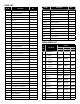
Thread Size
Tightening Torque,
Lb - In (Nm)
Length (L)
of Thread
G1/8 62 - 79 (7 - 9) 6 mm Max.
G1/4 106 - 125 (12 - 14) 8 mm Max.
G3/8 195 - 215 (22 - 24) 9 mm Max.
G1/2 250 - 270 (28 - 30) 12 mm Max.
Sealing Washer
Length of G parellel thread