
User's Manual
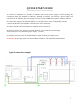


MAIN SCREEN
6
1
2
3 4
5
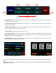
1. FWD Power Meter: Indicates the output power in operation mode with high accuracy. Note: The
measurement sometimes will not match with an external instrument due to loss from coax cables loss or
other devices connected to the transmission line. This loss can be up to 0.2 dBm.
2. REF Power Meter: Indicates the reflected power in Operation mode. Note: The measurement will
sometimes not match with external instruments due to the matching point of the transmission line. The
Amp will go into protection mode if REF is greater than 125 Watts.
3. Temperature Meter: Indicates the internal temperature, measured on the copper heat spreader to which
the LDMOS pair is soldered. Select °C/°F in the settings section.
4. Drain Voltage Meter: Indicates the voltage applied to the LDMOS pair in transmission. Note: This
voltage can sometimes vary slightly.
5. Drain Current Meter: Indicates the LDMOS pair drain current. This meter is not a reference for
LDMOS pair bias current.
6
9
7 8
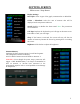
6. SWR Indicator: SWR does not determine the mercury Amp Protection feature, but it does influence the
output power.
7. Band Data Select: Indicates the Band Selector selected in the configuration section and the detected band.
Note: This is what is selected in the setup menu and may not be what is connected in the band data port.
8. Alarm Messages Zone: It shows the protection messages when the software algorithm activates the alarm:
CONTINUOUS CARRIER if >700 Watts. VOLTAGE ERROR if >55V. NOT OPERABLE 26-27 mhz.
OVER DRIVER if input power is high. HIGH D-CURRENT if >45A. HI TEMPERATURE if >65 °C/ 149 °F
REFLECTED >125 Watts.
9. On Air TAB: The indicator turns green when the amplifier is keying from the PTT port, the blue
underscore line appears when the RF level for RF Decoder is good.