
Install Instructions
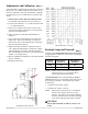

CEP-4000 Series 1 Installation Guide
Installation Guide
Mounting
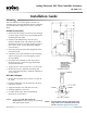
The CEP-4000 series are designed to mount on a
standard 1/2 in. (13 mm) diameter shaft or (using the
optional HFO-0011 adaptor) on a 3/8 in. (9.5 mm)
shaft.
Standard Instructions
1. Ensure that the damper can move freely through
its entire range of motion. Fix any binding before
installing the CEP-4000.
2. Slide the CEP-4000 directly onto the 1/2 in.
diameter damper shaft. The shaft must extend a
minimum of 1-3/4 in. from the mounting surface.
(For a 3/8 in. shaft, see the HFO-0011 Adaptor
section below.)
3. Place the non-rotation bracket (supplied) on the
non-rotation tab.
4. Aachthenon-rotationbrackettothemounting
surface using (2) #8 or #10 self-tapping screws
(not included).
5. Checkthatthestandos(ontheanti-rotation
bracket) provide a 1/8-inch air gap behind the
unit (see illustration).
6. Torque the two 5/16-18 setscrews to 75–85 in-lbs.
7. Mount the factory-calibrated, matching, SSE
series sensor horizontally to maintain calibration
atzeroairow.
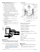
HFO-0011 Adaptor
1. Mount the CEP-4000 series actuator over the 3/8
in. shaft.
2. Slide the HFO-0011 over the shaft into the drive
hub of the actuator.
3. Align the adaptor slots with the setscrews.
4. Partially tighten the setscrews.
5. Continue with step 2 under the Standard
Instructions section above.
NOTE: See also the CEP-4995 Universal
Replacement section on page 4 if installing
that replacement model.
Mounting 1
Standard Instructions 1
HFO-0011 Adaptor 1
Wiring 2
Adjustments and Calibration 3
Rotation Setup and Override 3
CEP-4995 Universal Replacement 4
Maintenance 4
More Information 4
CEP-4000 Side View
HFO-0011 Adaptor
Analog Electronic VAV Flow Controller-Actuators
CEP-4000 Series
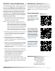
NOTE: For information about connections and
usage with newer CTE-5202 thermostats,
see the CTE-5202 Applications Guide.