
Manual

CME-7001/7002 Auxiliary Switches 1 Installation Guide
Installation Guide
Auxiliary Switches
CME-7001/7002
Mounting 1
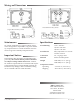
Wiring and Dimensions 2
Maintenance 2
Important Notices 2
Specifications 2
Mounting
These auxiliary switches are designed to start and
stop auxiliary items or to indicate an actuator’s fully
open or closed position. The single or dual switch
models are fully adjustable over the actuator’s 0 to
90° rotation. Switches are independently adjustable
for a trip point anywhere within the angular rotation
of the driving actuator.
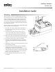
They are designed to mount on any KMC MEP-7000
Series Actuator as described here:
1. Insertthe“D”sha,foundontheundersideof
theswitchbox,intothe“D”hubontopofthe
actuator cover.
2. Fasten the switch box to the actuator with 4
screws (provided). This requires punching the
screws through the label on the actuator cover.
3. Depressthegeardisengagementbuon(red)and
rotate the actuator fully counterclockwise (CCW).
4. Loosen the center screw on the switch dial.
5. Turn the switch dial until the arrow on the dial
is pointing at the desired switching point on the
scale.
6. Tighten the center screw on the switch dial to lock
the switching position.
7. Verify the correct switching point by manually
rotating the actuator. The switch dial is
mechanically coupled to the actuator’s gear train
and will follow the actuator’s rotation. The switch
operates each time the arrow on the switch dial
passes “0” or “90” on the scale.
8. See the Wiring and Dimensions section on the
next page.
“D” Shaft
Screws