
Install Instructions

CSC-3000 Series 1 Installation Guide
Pneumatic VAV Reset Volume Controllers
CSC-3000 Series*
Mounting 1
Connections 1
Adjustments and Calibration 2
Damper Action 2
Adjusting Minimums and Maximums 2
DIRECT Reset Minimum and Maximum 2
REVERSE Reset Minimum and Maximum 2
More Information 2
Important Notices 2
Installation Guide
Mounting
CSC-3000 series controllers are position sensitive and must
be mounted and calibrated in either the horizontal or
vertical plane.
1. As near to the ow sensor pickup as is feasible,
connect the mounting bracket to the mounting surface
with two self-threading screws in the two 3/16" (5 mm)
mounting holes. Be sure to leave enough room to make
connections.
2. Insert the controller, face down, up, right or le. The
controller must be installed and adjusted in the same
plane or readjustment will be necessary.
Connections
All dimensions are in inches (mm)
CAUTION
Pneumatic devices
must be supplied with
clean, dry control air.
Any other medium
(e.g., oil or moisture
contamination) will
cause the device to fail.
*(These instructions do not apply to the CSC-3014 or the
CSC-3501/3505; see their separate Installation Guides.)
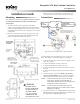
Magnehelic gauge and 0–30 psi
gauge in illustration added for
checkout and calibration purposes
Typical CSC-3011 Application and Connections
For all models of the CSC-3000 series, use 1/4" (5 mm)
O.D. “FR” tubing on the following push-on ings:
1. Connect the clean, dry, oil-free main air supply to Port
“M” (15 to 30 psi).
2. Connect the damper actuator to Port “B”.
3. Connect the thermostat output to Port “T”.
4. Connect the high pressure tap on the air ow sensor to
Port “H”.
5. Connect the low pressure tap on the air ow sensor to
Port “L”.
6. Check for proper connections. Make sure all tubes
are snug on their ings. If loose, trim the end of the
tubing and reconnect it to ensure there are no leaks.
NOTE: Over time, the tube may stretch or develop
microcracks. Trim the end of tube back to
undamaged material and reconnect. Replace the
tubing if it is brile or discolored.
NOTE: You can easily test for leaks with a squeeze
bulb to ensure there are no leaks at the actuator
diaphragm or ings.
7. Use a ow hood or “tee” a Magnehelic
®
(or equivalent)
dierential pressure gauge between the controller and
the ∆P pick-up to determine ow rates.
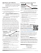
For adjusting start
point and span (upper
and lower knobs) see
the Application Guide
All adjustments
are CCW to
increase