
Application Guide

CSP-5001/5002 VAV Flow Controller-Actuators 4 Applications Guide, Rev. B
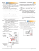
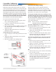
Air Flow Sensor Connection
Using 24 inches of 1/4-inch OD x 0.040-inch wall FR
instrument and control tubing, connect the CSP to an
SSS-1000 series dierential pressure ow sensor:
1. Connect the “H” port to the (high side) “H” of the
sensor.
2. Connect the “L” port to the (low side) “L” of the
sensor.
NOTE: To maintain a close correlation with the
factory calibration (for 0 to 3300 fpm),
installations, on both High and Low sides,
must use exactly 24 inches of the tubing
without restrictions such as ings or
kinks.
NOTE: The SSS-1000 series dierential pressure
ow sensor must be mounted with the
arrow pointing in the direction of the air
ow.
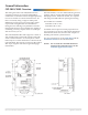
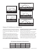
Rotation Setup
The CSP-5001 is factory-set for CCW to close. The
CSP-5002 is factory-set for CW to close. To reverse
the rotation direction of either controller model:
1. Remove the access door by pulling back on the
door’s tab and liing upward.
2. Position both jumpers in either the CW or CCW
positions as needed. See the diagram.
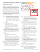
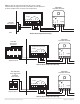
Wiring
1. Remove the CSP’s wiring access door by pulling
back on the door’s tab and liing upward.
2. Access for wire or cable is via two 5/8 in. (16 mm)
diameter snap-in shuer bushings located on the
rear of the CSP’s cover.
3. Connect conduit to the actuator if required
(connectors are not supplied—order separately):
A. HMO-4518 for 1/2 in. exible conduit.
B. HMO-4520 compression connector for plenum
rated cable.
C. HMO-4526 for rigid 1/2 in. conduit.
4. Remove snap-in shuer bushing and replace with
the HMO-4518 or HMO-4520 if required.
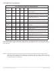
5. Connect the CSP to a CTE-5100 thermostat:
A. Terminal “16 VDC” to thermostat terminal
“+”.
B. Terminal “IN” to thermostat terminal “T1” for
cooling or “T2” for heating air ow.
NOTE: If minimum and maximum velocity limits
will be set at the CSP, then use “T3” for
cooling and “T4” for heating.
C. Terminal “OUT” to thermostat terminal “V1”
for velocity readout at thermostat.
D. Terminal “–” to thermostat terminal “–”.
6. Connect the CSP to a 24 volt AC, –15/+20%, 50/60
Hz power source:
A. Terminal “~” to the phase side of the 24 volt
AC transformer.
B. Terminal “–” to the neutral or ground side of
the transformer.
7. Replace wiring access door.