
Owner manual

CSP-5001/5002 1 Installation Guide
Installation Guide
Mounting
The CSP-5001/5002 is designed to mount on a stan-
dard 1/2 in. (13 mm) diameter shaft or a 3/8 in. (9.5
mm) shaft using the optional HFO-0011 adaptor.
Standard Instructions
1. Slide the CSP-500x directly onto the 1/2 in.
diameter damper shaft. The shaft must extend a
minimum of 1-3/4 in. from the mounting surface.
(For a 3/8 in. shaft, see HFO-0011 Adaptor on
page 1.)
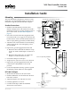
2. Place the non-rotation bracket (supplied) on the
non-rotation tab. Leave a gap of 1/8" between the
boom surface of the CSP-500x and the bracket to
allow for play during operation (see illustration).
3. Aach the non-rotation bracket to the mounting
surface using (2) #8 or #10 self-tapping screws
(not included).
4. Depress the gear disengagement buon and:
A. Rotate the drive hub until the indicator stops
at the “90” mark if the damper is clockwise to
close.
B. Rotate the drive hub to the “0” mark if the
damper is counterclockwise to close.
5. Position the damper to full open.
6. Torque the two 5/16-18 set screws 75 to 85 in-lb.
7. Depress the gear disengagement buon and
rotate the drive hub/damper to the closed
position.
8. Loosen the adjustable end stop, position against
the damper position indicator, and retighten.
HFO-0011 Adaptor
1. Mount the CSP-500x over the 3/8 in. shaft.
2. Slide the HFO-0011 over the shaft into the drive
hub of the actuator.
3. Align the adaptor slots with the set screws.
4. Partially tighten the set screws.
5. Continue with Step 2 under the Standard
Instructions section above.
Leave 1/8" Gap During Installation
VAV Flow Controller-Actuator
CSP-5001/5002
Mounting 1
Standard Instructions 1
HFO-0011 Adaptor 1
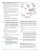
Wiring 2
Air Flow Sensor Connection 2
Maintenance 2
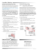
Controller Testing 3
Rotation Setup 3
Specications 3
More Information 3
Controller Calibration 4
Minimum and Maximum Flow Limits 4
VNOM (CFM) Range Setting 4
Important Notices 4