
User Guide

Installation Guide
Dual Temperature Room Thermostat
CTE –1003, 1004, 1103
Mounting
Standard:
• The base unit’s mounting slots are designed to align with the
holes in a standard 2" x 4" (51x102) handy conduit box.
• Use a 2" (51) deep box if using conduit.
• Normal screw and anchor systems may be used on solid
walls.
Hollow wall:
1. Cut a 3-3/4" x 1-3/4" rectangular opening in the wall.
(Check if unit is horizontal or vertical before cutting)
2. Make all necessary connections
3. Insert Toggle Bolt Assembly (HMO-5001, ordered separately)
through the wall and tighten.
Care should be taken not to bend or flex the base of the
thermostat.
Required Tools
• digital voltmeter
• small phillips screwdriver
• small flatblade screwdriver
• keyhole saw
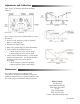
Wiring
Typically, T1 and T3 are used for cooling and T2 and
T4 are used for heating. Refer to the wiring
diagram.
CTE–1004 has a jumper installed from terminal
“A” to terminal “4”. This causes the thermostat to
switch to an auxiliary flow lever when a call for
heating begins. This flow level may be adjusted
under the cover . If auxiliary flow is not needed,
remove the jumper.