
User Guide

CTE-1001/1002/1101 1 Installation Guide
Installation Guide
Single Setpoint Room Thermostats
CTE-1001/1002/1101
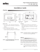
Mounting
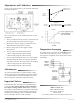
Wiring
Refer to the diagram above for screw terminal loca-
tions.
T3 is not restricted by the minimum and maxi-
mum control points. See the diagrams on the next
page. Typically in KMC thermostats, T1 and T3 are
used for cooling, and T2 and T4 are used for heating.
NOTE: Only CTE-1101s have the A terminal that
is used for temperature averaging. See the
Temperature Averaging section on the next
page.
Mounting 1
Wiring 1
Temperature Averaging 1
Important Notices 2
Maintenance 2
Standard:
• The base unit’s mounting slots are designed to
align with the holes in a standard 2" x 4" (51 x 102
mm) handy conduit box. Use such a box if using
conduit.
• On solid walls, normal screw and anchor systems
may be used.
NOTE: Seethedatasheetforacompletelistingof
accessoriesaswellasspecications.
Hollowwall:
1. Cut a 3-3/4" x 1-3/4" rectangular opening in the
wall. (Check if unit is horizontal or vertical before
cuing.)
2. Make all necessary connections.
3. Insert an HMO-5001 Toggle Bolt Assembly
(ordered separately) through the wall and tighten.
All dimensions are in inches (mm).
NOTE: Careshouldbetakennottobendorex
thebaseofthethermostat.