
User Manual

CTE-3016/3017/3026/3027 1 Installation Guide
Installation Guide
Low Limit Controllers, SPDT
CTE-3006/3007
Mounting 1
Wiring 1
Actuation and Reset 2
Setpoint Adjustment 2
Testing 2
Accessories 2
Maintenance 2
Specifications 2
Important Notices 2
Mounting
The controller can be mounted in any position,
but avoid locations subject to excessive vibration.
For manual reset models, position the controller to
permit convenient access to the reset buon.
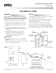
1. Loosen the front screw and remove the cover.
2. Using the two 3/8" mounting keyholes, mount
the case ush against the duct work or any at
surface.
3. Install the sensing capillary in a horizontal
serpentine fashion across the downstream side of
a water coil.
4. Using HMO-4523 capillary clips (ordered
separately), support the sensing capillary
at sucient points to prevent damage from
vibration and/or air movement.
CAUTION
Do not kink or apply excessive force to the capillary
element.
5. Make the appropriate connections to the terminal
blocks. (See the Wiring section.)
Wiring
An opening for installing a connector for 1/2" conduit
is provided in the boom of the case.
All wiring should comply with national and local
electrical codes. Using 10 to 14 AWG solid copper
wire is recommended.
Strip wire ends 3/8", insert the wire ends under
the cup washers on the switch block, and securely
retighten terminal screws. Wire terminals according
to the Actuation and Reset section on the next page.