
Owner manual

CTE-5100 Series 1 Installation Guide
Installation Guide
Electronic Room Thermostats
CTE-5100 Series
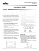
Mounting
General
CTE-5100 series thermostats require a scale plate
assembly and a cover, which must be ordered
separately. To ensure accurate temperature sensing,
mount thermostats on interior walls and away from
heat sources, sunlight, windows, air vents, and air
circulation obstructions (e.g., curtains and furniture).
These thermostats may be mounted horizontally or
vertically to a standard 2 x 4" (51 x 102 mm) handy
box using a HMO-5024/5026/5030/5031 backplate or
directly to a hollow wall using an HMO-5023 kit.
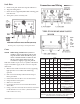
Electrical Box Mounting
1. Install, but DO NOT TIGHTEN, the HMO-
5024/5026/5030/5031 backplate to a handy box
using the two 6-32 screws (included).
2. Adjust and level the backplate using the sloed
mounting hole.
3. Tighten the two mounting screws.
4. Pull all thermostat wires and cable through the
backplate and decorative trim plate opening (of
the HMO-5024/5026/5030/5031). Be careful not to
damage the trim plate while wiring.
5. Connect the thermostat’s wires according to its
particular application. See the Connections and
Wiring section.
6. Position the trim plate between the backplate and
the thermostat (with the cover removed).
7. Align the mounting holes and secure the
assembly with the two 6-32 x 2" self-tapping
screws (included).
HMO-5024/5026/5030/5031 Back Plate
HMO-5023 Hollow Wall Mounting Kit (Screws Not Shown)
Hollow Wall Mounting
Thermostats may be mounted on a hollow wall up to
5/8" thick using the HMO-5023 hollow wall mount-
ing kit.
1. Using the template, cut a 1-1/2 x 2-11/16" opening
in the drywall.
2. Loosely mount the HMO-5023 bracket to the
thermostat (with cover removed) using the two
6-32 x 2" screws.
3. Pull all thermostat wires or cable through the
bracket’s wiring/cable access hole(s).
4. Connect the thermostat wires according to its
particular application. See the Connections and
Wiring section.
5. Insert bracket diagonally, through the wall
opening, and then center and tighten the screws.
Mounting 1
General 1
Electrical Box Mounting 1
Hollow Wall Mounting 1
Setpoint Stops 1
Scale Plate 2
Cover 2
Connections and Wiring 2
Adjustments and Calibration 4
Maintenance 4
More Information 4
Important Notices 4
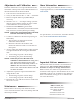
Setpoint Stops
Optional setpoint stops can be used to lock or limit
the setpoint range. Each HFO-0027 setpoint stop
strip (accessory sold separately) contains four stops.
1. Break a stop from the strip by gently folding on
the seam with pliers.
2. Insert a stop into the slider track on one or both
sides of the slider.
3. Repeat for second slider.
HFO-0027 Setpoint Stop Strip