CTE-5202 Analog Electronic Thermostat w/ LCD Display Applications Guide Contents General Information (All Applications)................................................................................... 3 Important Notices...........................................................................................................................................................4 Accessories........................................................................................................................
Pressure Independent VAV Applications with CSP-4702....................................................... 19 Replacing a CSP-5001/5002..........................................................................................................................................20 Replacing a CEP-4xxx or CSP-40xx/42xx/44xx/46xx or CSE-484x................................................................................21 Cooling or Heating............................................................................
General Information (All Applications) This document gives schematics of sample (new and retrofit) applications, cross-references, troubleshooting, and other related information. For general mounting and connection details, including power connections and input/output connections, see the CTE-5202 Installation Guide. For specifications and other information, see the CTE-5202 Data Sheet. The latest support files are always available on the KMC Controls web site (www.kmccontrols.com).
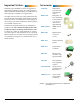
Important Notices Accessories The KMC logo and KMC Controls are registered trademarks of KMC Controls, Inc. Other products and name brands mentioned may be trademarks of their respective companies or organizations. CSP-4702 Differential pressure VAV controller/actuator All rights reserved. No part of this publication may be reproduced, transmitted, transcribed, stored in a retrieval system, or translated into any language in any form by any means without the written permission of KMC Controls, Inc.
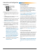
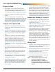
Connection and Configuration Connections External Input (AI1) Hot/Cold Changeover “Heating” Output “Cooling” Output Input Common Common Power (AC Phase or DC +) AO2 AO1 AI1 T T ~ For hot/cold air changeover on Sequence 1 or 2, connect a changeover sensor to the AI1 input. The sensor should be a Type III thermistor (10K ohm @ 77° F), such as KMC STE-140x duct or STE1454/1455 strap-on sensors. (An internal 10K ohm pullup resistor is provided on AI1.
MAX = 12, and AUX = 0 as defaults.) Use the Up and Down buttons to change the desired values. (If no Auxiliary Flow is desired, set AO1 AUX to 0.) Change Setpoint To change the setpoint: 1. Push the Setpoint button (or either Up/Down button) to display the current value. NOTE: To change any of the system or advanced features, press the Up or Down button until the desired (flashing) ADVANCE or SYSTEM menu appears and then press the Setpoint button.
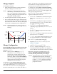
Sequences HOT AIR SEQUENCE (Morning Warm Up) COLD AIR SEQUENCE 12 Volts AO2 Disabled (12 Volts) AO1 (DA) AO1 (RA) AO2 (DA) 0-12 Volts 6 Volts AO1 MAX AO1 MAX AO1 MIN AO1 MIN 2° F Temp.
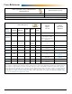
Cross-References Barber Colman (TAC, Invensys, Schneider Electric) CTE-5202 Sequence Selected Thermostat Replaced TP-8101, TP-8102, and TP-8103 #1 TP-8124 and TP-8125 #3 For wiring and sample applications, see Barber Colman TP-81xx Thermostats Replacement Applications on page 54.
KMC CTE-50xx CTE-5202 Sequence Selected Example Replacement Applications CTE-5001/5011* #1 See page 45 and page 48 (9.1 VDC) CTE-5002/5012* #2 See page 47 (9.1 VDC) CTE-5003/5013* (No Replacement) (9.1 VDC) CTE-5006/5016** #2 See page 35 (16 VDC) CTE-5015** #1 See page 33 (16 VDC) Thermostat Replaced *NOTE: These models require a power supply of 9.1 VDC, typically supplied by a CEP/CSP-4xxx controller/actuator, and they have a 0–6 VDC output range. See the discussion on 9.
CTE-5202 Troubleshooting • Display Is Blank • If the display comes on for no more than 30 seconds after a button is pushed and then blanks out, Display Blanking is enabled in the SYSTEM menu. See Change Configuration on page 6. • Check for a tripped circuit breaker to the transformer.
Single-Zone Proportional Heating and Cooling Applications This section gives sample applications for using the CTE-5202 in single zone proportional heating (baseboard heaters) and cooling (chilled beams) with valves or SCR control. For chilled beam applications, separate control of humidity is required to prevent condensation.
Heating, RA and DA CTE-5202 thermostats can use a variety of valves for heating/cooling applications with hot and chilled water. For Reverse Acting control, connect a 5K to 10K ohm resistor between Common and AI1. Select Sequence 1 (from the CTE-5202 SYSTEM menu) and lower the Changeover (in the ADVANCE menu) to the lowest setting (55° F). See Change Configuration on page 6. The resistor simulates a changeover sensor and puts the thermostat in Reverse Acting mode.
Chilled Beam Cooling This application controls cooling in a chilled beam or equivalent installation. Select Sequence 1 (from the CTE-5202 SYSTEM menu). See Change Configuration on page 6. This works for NC 2–10 and 0–10 VDC valves or NO 10–2 and 10–0 VDC valves. CTE-5202 Select Sequence 1 Input 24 VAC Valve Common ~ T T AO2 AO1 AI1 Thermostat 24 VAC (Neutral) – (Phase) ~ Cooling Max. Cooling Min.
Chilled Beam 4-Pipe Heating and Cooling This application enables both heating and cooling in a chilled beam and baseboard or equivalent installation. Select Sequence 3 from the CTE-5202 SYSTEM menu. See Change Configuration on page 6. This works for NC 2–10 and 0–10 VDC valves or NO 10–2 and 10–0 VDC valves.
Chilled Beam 2-Pipe Heating and Cooling with Changeover An STE-1454/1455 strap-on (Type III) temperature sensor provides the CTE-5202 an automatic changeover for heating/cooling applications using hot and chilled water. The sensor will switch the thermostat between cooling and heating modes based on the temperature of the water in the pipe.
Pressure Dependent VAV Applications with MEP-4xx2 This section gives sample applications for using the CTE-5202 with the MEP-4xx2 actuator in pressure dependent VAV applications. The MEP-4xx2’s default direction is CCW to close (CW to open or CW with increasing voltage), but this can be reversed by a switch during installation and configuration. See also the MEP-4000 Series Installation Guide.
Cooling or Heating CTE-5202 thermostats can use MEP-4xx2 actuators to operate damper boxes in a pressure-dependent VAV system. As shown in the diagram, a “requested flow” voltage signal (AO1) is connected to the MEP4002 to adjust airflow from minimum to maximum flow according to space demand. Minimum and maximum flow limit adjustments can be made at the thermostat (recommended) or at the actuator. (See the MEP-4000 Series Installation Guide.
Auto and Override (to Fully Closed) Adding a Normally Closed SPST relay or switch enables overriding the air flow to fully closed. (Otherwise the example below is the same as the configuration in Cooling or Heating on page 17). NOTE: An override to fully open does not apply to the MEP-4xx2 in a way that is analogous to the CSP-5001 as shown in Auto and Override (to Fully Closed or Fully Open) on page 34. The default setting is Auto.
Pressure Independent VAV Applications with CSP-4702 This section describes using the new CSP-4702 VAV controller-actuators in new installations as well as in the place of older CSP-5001/5002, CEP-4xxx, and CSP-40xx/42xx/44xx/46xx VAV controller-actuators. The CSP-4702 uses a differential pressure sensor rather than the flow sensors of the older models.
Replacing a CSP-5001/5002 The CSP-4702 can be used in any of the CSP5001/5002 applications shown in the section Pressure Independent VAV Applications with CSP-5001/5002 on page 32. However, there are some differences among the models of which the installer must be aware: • • Output torque of the CSP-4702 is 40 in. lb. instead of the CSP-500x’s 50 in. lb. Check torque requirements of the damper when replacing a CSP-500x.
Replacing a CEP-4xxx or CSP-40xx/42xx/44xx/46xx or CSE-484x With changes to the sensors, the CSP-4702 can generally be used in any of the older CEP-4xxx and CSP-40xx/42xx/44xx/46xx applications shown in the section Pressure Independent VAV and CAV Applications with CEP/CSP-4000 Series on page 43.
Cooling or Heating CTE-5202 thermostats can use CSP-4702 electronic VAV controllers to operate damper boxes in the pressure-independent VAV system. As shown in the diagram, a “requested flow” voltage signal (AO1) is connected to the CSP-4702 to adjust airflow from minimum to maximum flow according to space demand. Minimum and maximum flow limit adjustments can be made at the thermostat or at the controller. For heating, connect a 5K to 10K ohm resistor between Common and AI1.
Auto and Override (to Fully Open) Adding a SPDT relay or switch enables overriding the air flow to fully open. (Otherwise the example below is the same as the cooling configuration in Cooling or Heating on page 22.) NOTE: If a maximum limit was set in the CSP-4702 controller, the damper will only open to the maximum limit setting. See also the Operation Test section of the CSP-4702 Installation Guide. The SPDT relay selects one of the two modes (Auto/ Open).
Cooling with 3-Stage Reheat This application uses a CSP-4702 along with an REE-5001 relay module and three 24 VAC contactors for three stages of reheat. Select Sequence 2 (from the CTE-5202 SYSTEM menu), with or without Auxiliary Flow (AO1 AUX in LIMITS menu). See Change Configuration on page 6. As the temperature drops below setpoint, the first stage of reheat begins. As the temperature continues to drop, the second stage and later the third stage begin as needed.
Cooling with 3-Stage Reheat and Night Setback/Setup NOTE: The night/unoccupied setback offset does not apply to morning warm-up. This configuration is the same as on the previous page except for the addition of an SPST relay or switch. See Cooling with 3-Stage Reheat on page 24. The switch or relay is driven by a night/unoccupied setback/setup signal from other equipment not shown. When the contact is closed (e.g.
Cooling with Heating Changeover Using a duct sensor with the CTE-5202, an automatic changeover is provided for cooling/heating applications. The duct sensor will switch the thermostat between cooling and heating modes based on the temperature of the duct supply air. A duct temperature higher than changeover temperature switches control to heating mode, and a temperature lower than changeover temperature switches control to cooling mode. Select Sequence 1 (from the CTE-5202 SYSTEM menu).
Cooling with Heating Changeover and Electric Reheat This configuration is the same as the previous page except for the addition of an REE-5001 relay module connected to AO2 (for three stages of reheat) and selecting Sequence 2 from the CTE-5202 SYSTEM menu. See Change Configuration on page 6, Hot/ Cold Changeover on page 5 and Cooling with Heating Changeover on page 26. See also Cooling with 3-Stage Reheat on page 24.
Cooling with Heating Changeover and Hot Water Reheat See Cooling with Heating Changeover and Electric Reheat on page 27. This application operates the same except for using a hot water valve instead of electric heating elements for reheat (a VEB-43/46 series valve in place of the REE-5001 relay). When there is hot air in the duct, changeover initiates, allowing the heating signal from AO1 to control airflow and AO2 to control the valve.
Cooling with Hot Water Reheat See Cooling with 3-Stage Reheat on page 24. This application operates the same except for using a hot water valve instead of electric heating elements for reheat (a VEB-43/46 series valve in place of the REE5001 relay). AO1 controls airflow and AO2 controls the valve. When there is a call for heat, the thermostat modulates the hot water valve.
Fan Induction with 2-Stage Electric Heat This fan induction application uses the thermostat with a REE-5002 relay module, a fan, and two coils (for two stages of reheat). The REE-5002 was designed primarily for use with VAV fan-powered induction boxes. NOTE: The REE-5002 provides the fan an adjustable start point between 3 and 8 VDC, with a 1 VDC switching differential. The “X” Terminal is used for measuring fan trip voltage. See the REE-5002 Installation Guide for details.
Dual Duct, Minimum Air from Cold Duct Dual duct applications can use two CSP-4702s with a CTE-5202. In this application, the CSP-4702s are mounted separately on the cold and hot air duct dampers with each using its own flow sensor. receives its requested flow signal from AO2. Both CSP-4702s can be set independently for minimum and maximum flow settings. Select Sequence 3 (from the CTE-5202 SYSTEM menu). See Change Configuration on page 6.
Pressure Independent VAV Applications with CSP-5001/5002 This section gives sample applications for using the CTE-5202 as a substitute for the CTE-5100 series thermostats with the CSP-5001/5002 VAV controlleractuator. (For replacement of the CSP-500x by the CSP-4702, see Replacing a CSP-5001/5002 on page 20.) Factory-set rotation direction of the CSP-5001 is CCW to close (CW to open or CW with increasing voltage), and the CSP-5002’s is CW to close (CCW to open or CCW with increasing voltage).
Cooling or Heating CTE-5202 thermostats can use CSP-5000 series electronic VAV controllers to operate damper boxes in the pressure-independent VAV system. As shown in the diagram, a “requested flow” voltage signal (AO1) is connected to the CSP-5001 to adjust airflow from minimum to maximum flow according to space demand. Minimum and maximum flow limit adjustments can be made at the thermostat or at the controller. For heating, connect a 5K to 10K ohm resistor between Common and AI1.
Auto and Override (to Fully Closed or Fully Open) Adding a SPDT relay or switch enables overriding the air flow to fully open or fully closed. (Otherwise the examples below are the same as the cooling configuration in Cooling or Heating on page 33.) The “Override to Fully Open” wiring illustration below allows the CTE-5202 thermostat to control the CSP-5001 controller as normal (Auto) or override the flow setting to fully open.
Cooling with 3-Stage Reheat This application uses a CSP-5001 along with an REE-5001 relay module and three 24 VAC contactors for three stages of reheat. Select Sequence 2 (from the CTE-5202 SYSTEM menu), with or without Auxiliary Flow (AO1 AUX in LIMITS menu). See Change Configuration on page 6. As the temperature drops below setpoint, the first stage of reheat begins. As the temperature continues to drop, the second stage and later the third stage begin as needed.
Cooling with 3-Stage Reheat and Night Setback/Setup This configuration is the same as on the previous page except for the addition of an SPST relay or switch. See Cooling with 3-Stage Reheat on page NOTE: This configuration requires the system fan to be on during setback/setup mode. NOTE: Triac outputs on the REE-5001 are for 24 VAC loads only. The phase side of the transformer connects to the “common” side of the load (contactors). 35.
Cooling with Heating Changeover Using a duct sensor with the CTE-5202, an automatic changeover is provided for heating/cooling applications. The duct sensor will switch the thermostat between cooling and heating modes based on the temperature of the duct supply air. A duct temperature higher than changeover temperature switches control to heating mode, and a temperature lower than changeover temperature switches control to cooling mode. Select Sequence 1 (from the CTE-5202 SYSTEM menu).
Cooling with Heating Changeover and Electric Reheat This configuration is the same as the previous page except for the addition of an REE-5001 relay module connected to AO2 (for three stages of reheat) and selecting Sequence 2 from the CTE-5202 SYSTEM menu. See Change Configuration on page 6, Hot/ Cold Changeover on page 5 and Cooling with Heating Changeover on page 37. See also Cooling with 3-Stage Reheat on page 35.
Cooling with Heating Changeover and Hot Water Reheat See Cooling with Heating Changeover and Electric Reheat on page 38. This application operates the same except for using a hot water valve instead of electric heating elements for reheat (a VEB-43/46 series valve in place of the REE-5001 relay). airflow and AO2 to control the valve. When there is a call for heat, the thermostat modulates the hot water valve.
Cooling with Hot Water Reheat See Cooling with 3-Stage Reheat on page 35. This application operates the same except for using a hot water valve instead of electric heating elements for reheat (a VEB-43/46 series valve in place of the REE5001 relay). (See also the Cooling with Hot Water Reheat section with a CTE-5104 in the CSP-5001/5002 Applications Guide.) NOTE: See also the use of the CTE-5202 with discontinued VEP-12/22/34 series valves in Cooling with Hot Water Reheat on page 49.
Fan Induction with 2-Stage Electric Heat In this fan induction application, the CTE-5202 thermostat is used with a REE-5002 relay module, a fan, and two coils (for two stages of reheat). The REE-5002 was designed primarily for use with VAV fan-powered induction boxes. (See also the Fan Induction with 2-Stage Electric Heat section with a CTE-5101 in the CSP-5001/5002 Applications Guide.) NOTE: If the temperature drops below setpoint, the REE5002 senses the decrease in voltage on AO2 and starts the fan.
Dual Duct, Minimum Air from Cold Duct Dual duct applications can use two CSP-5001s with a CTE-5202. In this application, the CSP-5001s are mounted separately on the cold and hot air duct dampers with each using its own flow sensor. Select Sequence 3 (from the CTE-5202 SYSTEM menu). See Change Configuration on page 6. (See also the Dual Duct, Minimum Air from Cold Duct section with a CTE-5103 in the CSP-5001/5002 Applications Guide.
Pressure Independent VAV and CAV Applications with CEP/CSP-4000 Series This section gives sample applications for using the CTE-5202 as a substitute for the CTE-1000 series thermostats with the CEP/CSP-4000 series VAV controller-actuators. (See also the CEP-4000 Series Applications Guide. For replacement of the CxP4xxx with the CSP-4702, see Replacing a CEP-4xxx or CSP-40xx/42xx/44xx/46xx or CSE-484x on page 21.) The CEP-4000 series uses SSE-1000/2000 series flow (“hot wire anemometer”) sensors.
9.1 VDC vs. 24 VAC Power Options The CTE-5202 can operate from the 9.1 VDC output supplied by the CEP/CSP-4xxx, but AO1 and AO2 will not be able to attain a full 6 VDC (e.g., a maximum of about 5.3 VDC) output to the 0–6 VDC CEP/ CSP-4xxx inputs. This means the maximum air flow controlled by the CEP-4xxx can be only around 2000 fpm instead of 3000 fpm. However, this will still cover nearly all applications. If more than about 2000 fpm is required, use 24 VAC from a transformer to power the CTE-5202.
Cooling CTE-5202 thermostats can use CEP/CSP-4000 series electronic VAV controllers to operate damper boxes in a pressure-independent VAV system. As shown in the diagram, a “requested flow” voltage signal (AO1) is connected to the CEP-4xxx to adjust airflow from minimum to maximum flow according to space demand. Minimum and maximum flow limit adjustments can be made at the thermostat or at the controller. Select Sequence 1 (from the CTE-5202 SYSTEM menu). See Change Configuration on page 6.
Cooling with Morning Warm-Up Using the thermistor in an SSE-2001/2002 sensor enables the sensing of morning warm-up, and adding a SPDT relay or switch enables overriding the air flow to fully open for morning warm-up. Otherwise the example below is the same as the configuration in Cooling on page 45. connected to either Terminal 5 (Fully Open) or to AO1 on the CTE-5202 (Auto, the default). When Terminal 6 is connected to Terminal 5, the 9.1 VDC causes full flow.
Cooling with 3-Stage Reheat The application below uses an SSE-1000 series sensor, an REE-4001/5001 relay module, and three 24 VAC contactors for three stages of reheat. The transformer must supply a minimum of 10 VA plus the requirements for the reheat contactor coils (10 VA maximum per stage). CEP-4xxx Controller-Actuator 24 VAC @ 40 VA 8 7 (Neutral) – 9 6 (Phase) ~ 10 5 11 4 12 3 13 2 14 1 If no Auxiliary Flow is desired, set AO1 AUX to 0 in the LIMITS menu.) 2 3 9.5 V 6.5 V 3.
Cooling with Heating Changeover Using a duct sensor with the CTE-5202, an automatic changeover is provided for cooling/heating applications. The duct sensor will switch the thermostat between cooling and heating modes based on the temperature of the duct supply air. A duct temperature higher than changeover temperature, switches control to heating mode, and a temperature lower than changeover temperature, switches control to cooling mode. Select Sequence 1 (from the CTE-5202 SYSTEM menu).
Cooling with Hot Water Reheat See Cooling with 3-Stage Reheat on page 47. This application operates similarly except for using a hot water valve instead of electric heating elements for reheat. CEP-4xxx Controller-Actuator The CTE-5202 here replaces a CTE-1004 (DA cooling and 24 VAC @ 12 VA RA heating) and is used in (Neutral) – conjunction with an REE(Phase) ~ 4006 time proportioning relay module and a (NC) VEP12/22/34 series hot water valve.
Fan Induction with 2-Stage Electric Heat In this fan induction application, the CTE-5202 thermostat is used with a REE-4002/5002 relay module, a fan, and two coils (for two stages of heat). The REE-4002/5002 was designed primarily for use with VAV fan-powered induction boxes. Sequence 1 should be selected from the CTE-5202 SYSTEM menu. See Change Configuration on page 6. (See also the Fan Box with Reheat section with a CTE-1101 in the CEP-4000 Series Applications Guide.
Damper Tracking (Master/Slave) The configuration is used for special applications where a differential pressure is needed (either positive or negative). The thermostat controls the “master” CEP-4xxx controller-actuator and a (discontinued) REE-1013 relay controls the “slave.” The relay takes the voltage reading from the master CEP-4xxx and repeats it to the slave CEP-4xxx plus or minus a given offset.
Dual Duct Heating and Cooling VAV Dual duct applications connect two CEP-4000 series controllers, mounted separately on the hot and cold air-duct dampers, with each controller using its own flow sensor. The hot deck controller receives its requested flow signal from AO2 on the CTE-5202, while the cold deck uses the AO1 signal. Both controllers can be set independently for minimum and maximum flow settings. Sequence 3 should be selected from the CTE-5202 SYSTEM menu. See Change Configuration on page 6.
Dual Duct Heat/Cool Constant Volume with Hot Deck Make-Up This application is designed for dual-duct installations requiring constant air volume (CAV). In this application, a single-duct cooling controller is mounted on the cold air duct, and its minimum and maximum flow is reset by the room thermostat. A second “slave” controller is mounted on the hot air duct as a constant volume unit, with the flow sensor measuring downstream “total flow” into the space.
Barber Colman TP-81xx Thermostats Replacement Applications This section gives sample applications for using the CTE-5202 in the place of a Barber Colman (TAC, Invensys, Schneider Electric) TP-81xx thermostat. Some of the applications include use with MP-52xx “beer can” actuators.
TP-8101/8102/8103 Replacement (General) CTE-5202 thermostats can replace TP-8101/8102/8103 thermostats and use the 20 VDC supplied by a controlled device. (For more information, see the manufacturer’s installation guide for the controlled devices.) For cooling, select Sequence 1 (from the CTE-5202 SYSTEM menu). See Change Configuration on page 6. For heating, connect a 5K to 10K ohm resistor between Common and AI1. Select Sequence 1 and lower the Changeover to the lowest setting (55° F).
TP-8101/8102/8103 Replacement with MP-52xx Actuators See TP-8101/8102/8103 Replacement (General) on page 55. This is the same configuration except for the addition of MEP-52xx actuators and changes to the connections to the red leads.
TP-8124/8125 Replacement with One or No MP-52xx Actuators CTE-5202 thermostats can replace TP-8101/8102/8103 thermostats and use the 20 VDC supplied by a controlled device. (For more information, see the manufacturer’s installation guide for the controlled devices.) Select Sequence 3 (from the CTE-5202 SYSTEM menu). See Change Configuration on page 6.
TP-8124/8125 Replacement with Two MP-52xx Actuators See TP-8124/8125 Replacement with One or No MP52xx Actuators on page 57. This is the same configuration except for having two MEP-52xx actuators and changes to the connections to the red leads.
Index Symbols CSP-4000 (CSP-40xx/42xx/44xx/46xx) ControllerActuators: 21, 43 CSP-4702 Controller-Actuator: 19 CSP-5001/5002 Controller-Actuators: 20, 32 CTE-1x0x Cross-Reference: 8 CTE-50xx Cross-Reference: 9 CTE-510x Cross-Reference: 9 CTE-1001 Replacement: 45 CTE-1004 Replacement: 47, 49 CTE-1101 Replacement: 45, 50, 51 CTE-1103 Replacement: 48, 52, 53 CTE-5001/5011 Replacement: 45, 48 CTE-5002/5012 Replacement: 47 CTE-5006/5016 Replacement: 24, 35 CTE-5015 Replacement: 22, 33 CTE-5101 Replacement: 9, 33
L SSE-1001/1002 Flow Sensors: 45, 47, 49, 50, 51, 52, 53 SSE-2001/2002 Flow/Temp. Sensors: 46, 48 SSS-10xx Flow Sensors: 19 Standby (Setback): 5 Static Pressure Controller: 19 STE-140x Duct Sensor: 37, 38, 39 STE-1454/1455 Strap-On Temp.