
User guide

HLO-4001 1 Installation Guide
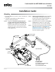
KIT INCLUDES:
(1) Crank Arm
(2) 1/4-28 X 3/4" Cap Screws
(2) 1/4-28 Hex Nuts
(2) VTD-0804 Ball Joints
5/16" Dia. Rod
(not included)
VTD-0804
Ball Joints
Crank
Arm
1/4-28X3/4"
Cap Screw
1/4-28
Hex Nut
(Not included)
(3) Mounting Holes
for #8 screws
(not included)
Mounting
1. From the MEP-4xxx actuator, remove and discard
the V-bolt.
2. Assemble and install the kit and actuator as
shown in the diagram below.
NOTE: In general, position both the ball joints
as close to the end of the crank arms as is
feasible for the application. Positioning a
ball joint in the slot closer to the shaft will
change the torque, rotation speed, and/or
angle of rotation—which may be useful for
some applications.
Installation Guide
Crank Arm Kit for MEP-4000 Series Actuators
HLO-4001
Mounting 1
Maintenance 2
Accessories 2
More Information 2
Important Notices 2
NOTE: Check for potential issues such as binding
of the linkage or damage caused by the
actuator still rotating when the damper (or
other application) is already closed.
NOTE: See the Accessories section for an auxiliary
crank arm if the damper or other equip-
ment does not have one already installed.
NOTE: For much more information about installing
MEP-4xxx actuators, see the MEP-4xxx
Applications Guide on the KMC web site
(www.kmccontrols.com) as well as the
relevant installation guide.