Installation and Operation Guide NetSensor ® KMD-1162 Temperature sensor Contents Specifications ............................................................... 2 Network Cable Preparation .......................................... 4 Rough-in preparation ................................................... 5 Installing the NetSensor ................................................ 5 Operation .................................................................... 6 Maintenance .................................
KMD–1162 Installation and Operation KMC Controls Specifications Display LCD, 2-character, 7-segment, 056. in. high. Compatibility KMD-5800 series controllers KMD-7000 series controllers BAC-5800 series BACnet controllers BAC-7000 series BACnet controllers Connection Connector type Cable length PC port RJ–12 connects data and power to compatible controllers Maximum 75 feet (22.
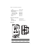
KMD–1162 Installation and Operation White HMO–1161W Replacement allen screw HPO–0044 Network cables 25 feet (7.6 meters) 50 feet (15.2 meters) 75 feet (22.9 meters) Interface Cable Gasket KMD–5690 KMD–5691 KMD–5692 KMD–5624 HPO–1161 Sensor type and accuracy 10k thermistor ±2° F (±1.1° C) 47 to 97° F (8 to 36° C) Type Accuracy Operating range Dimensions A B CD E A B C D E 3.25 in. 5.16 in. 2.58 in. 3.25 in. 0.87 in.
KMD–1162 Installation and Operation KMC Controls Models Almond White KMD-1162-10 KMD-1162W10 Network Cable Preparation Connecting a NetSensor to a KMC controller requires a six-wire cable with RJ-12 connectors on each end. Use either the KMC Controls ready-to-use cables or make cables to length when the NetSensor is installed. Cables made to length must meet the following requirements: ◆ Cable length is no longer than 75 feet (22.9 meters). Use cable with #24 AWG size conductors.
KMD–1162 Installation and Operation Rough-in preparation Complete rough-in wiring at each sensor location prior to sensor installation. This includes the following. ◆ Route the network cable from the NetSensor location to the controller to which it will connect. ◆ If required, install the appropriate mounting backplate. See Accessories on page 2 for model numbers.
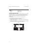
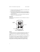
KMD–1162 Installation and Operation KMC Controls 3. Fasten the mounting base to the backplate or the outlet box with the Allen screws toward the floor. 4. Insert the RJ-12 cable coming from the base into the NetSensor. 5. Place the top of the NetSensor over the top of the mounting base and swing it down over the Allen screw brackets. Be careful not to pinch any wiring. 6. Back the Allen screws out of the brackets until they engage the NetSensor cover and hold it in place.
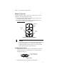
KMD–1162 Installation and Operation Changing the setpoint Pressing either the up or down setpoint buttons changes the display from room temperature mode to setpoint mode. Pressing either button once displays the current setpoint for three seconds; each additional press increments or decrements the setpoint temperature by one degree Fahrenheit. Backlight When either setpoint button is pressed the backlight turns on and remains on for 10 seconds after the last button is released.
KMD–1162 Installation and Operation KMC Controls Important notices The KMC logo, WinControlXL and NetSensor are registered trademarks of KMC Controls, Inc. TotalControl and BACstage are trademarks of KMC Controls, Inc. ©2012, KMC Controls, Inc. All rights reserved. No part of this publication may be reproduced, transmitted, transcribed, stored in a retrieval system, or translated into any language in any form by any means without the written permission of KMC Controls, Inc. Printed in U.S.A.