
User guide

XEC-3001/3002/3004 1 Installation Guide
Installation Guide
E/I–P Transducer
XEC-3001/3002/3004
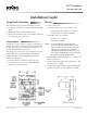
(Snap Track) Mounting
The transducers may be mounted in any position.
1. Carefully remove the circuit board from the Snap
Track.
2. Mount the track in the desired location.
3. Replace board in the track. Do not slide or ex the
circuit board while replacing.
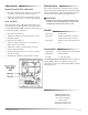
Wiring
1. Connect the power.
a. 24 VAC (+20%/–15%, Class 2 Only, 1 VA):
• Transformer phase lead to “~” (phase).
• Neutral lead to “GND” (common).
b. 24 VDC (+66%/–8%, 50 mA):
• Positive to “~” (phase).
• Negative to “GND.”
NOTE: Any other device connected to this
(Class 2 only) transformer must use the
same common. If you are not sure of the
other device’s polarity, use a separate
transformer. If the shared device is a coil,
use a spike-snubbing device across the coil
to prevent possible malfunctions.
2. Position Input Program Jumper to 1–5 VDC, 2–10
VDC, or 4–20 mA.
3. Connect the input signal wiring, positive to “IN”
and negative to “GND.”
4. Connect the output feedback signal (if required)
positive to “OUT 1–5” and negative to “GND.”
Connections
A clean, dry, oil-free main air supply is required for
proper operation. An internal, non-replaceable lter
is used. If air supply contamination is suspected, use
an external HFO-0006 in-line lter.
The gauge port will accept a 1/8" male NPT pressure
gauge. This allows direct reading of the pressure
output. This port must be plugged if a pressure
gauge is not required.
1. Connect the 20 psi main air to the “M” port.
2. Connect the “B” port to the controlled device
(damper or valve actuator).
(Snap Track) Mounting 1
Connections 1
Wiring 1
Adjustments 2
Manual Override (XEC-3004 Only) 2
Span and Zero 2
Maintenance 2
Models 2
Accessories 2