
Installation Guide
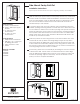


Slide the telescopic upper section of the pantry into the top of the lower
section. NOTE: for frameless cabinet installation, the locator tab on the
front mounting flange of the top slide will need to be flattened. In addi-
tion, the rear socket should be removed and the slide should be at-
tached directly to the cabinet.
To correctly place the unit in the cabinet, place assembled unit in the
cabinet opening and hang baskets on both sides. Then, slide unit in and
out of cabinet to make sure it can clear opening and operate correctly.
Adjust the telescopic upper section so that the front mounting flange on
the top slide is flush with the bottom of the face frame or cabinet shelf.
NOTE: if inset or lip door is used, clearance allowances will need to be
made for top and bottom slides.
Mark the position for holes using the slots in the bottom slide. Also mark
screw holes for the top slide’s mounting flange. Adjust the top slide’s
rear socket depth by sliding the socket until it is flush with the back wall
of the cabinet and mark holes. Drill pilot holes using previous marks. Use
3/4" screws to fasten unit to cabinet floor. Use 1/2" screws to fasten front
mounting flange and rear socket to cabinet.
If necessary, plumb the unit vertically by loosening the screws in the slots
of the bottom slide. Check action for vertical and front-to-back align-
ment by sliding the installed unit in and out of the cabinet to make sure
it clears the opening. Adjust as necessary. Mount the baskets on the
pantry’s hooks to complete installation.
Side-Mount Pantry Roll-Out
Installation Instructions
RN-256EFS-B-0810
Inspect all parts and read all instructions prior to beginning assembly and installation.
©2010 Knape & Vogt. All rights reserved. Knape & Vogt
®
reserves the right to change specifi cations without notice. Made in USA.
2700 Oak Industrial Drive NE
Grand Rapids, MI 49505 USA
800.253.1561 • www.kv.com
Parts Included
A. Pantry, Lower Section
B. Pantry, Telescopic Upper
Section
C. 6 – #8 x 3/4" Truss
Head Screws
D. 3 – #8 x 1/2" Truss
Head Screws
Tools Required
• Phillips head screwdriver
• Drill with 1/16” (1.5mm) bit
for drilling pilot holes
• Tape measure or ruler
• Pencil
May be used with:
P4250FE
P4650FE
P5450FE
P6500FE
1
2
1
2 3
3
4