
Installation Guide
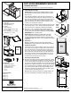
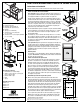

Parts Included
A. Waste Bin(s)
B. Sliding Base Assembly (1)
C. Waste Bin Chassis (1)
D. Template
E. Lid(s) (if supplied)
F. #8x1/2" Mounting Screws for Door
(8 = 4 + 4 extra)
G. #8X1" Mounting Screws for Sliding
Assembly (8 = 6 + 2 extra)
Tools Required
• Phillipsheadscrewdriver
• Drillwith1/16"(1.5mm)bit
for drilling pilot holes
• Tapemeasureorruler
• Pencil
• Scissors
Product Assemblies
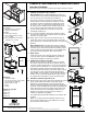
USC12-1-35
USC12-1-50
USC15-2-35
USC18-2-50
SOFT-CLOSE UNDERMOUNT WASTE BIN
Installation Instructions
Inspect all parts and read all instructions prior to beginning assembly and installation.
310188-E-0814
2700 Oak Industrial Drive NE , Grand Rapids, MI 49505 USA
800.253.1561 • 616.459.3311 • www.kv.com
©2014 Knape & Vogt. All rights reserved. Made in USA.
Knape & Vogt
®
reserves the right to change specications without notice.
4A
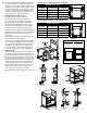
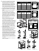
1. Install Sliding Base Assembly
Optional Step: Place slide assembly installation template on cabinet
floor. Drill 6 holes at locations shown on template with 1/16" drill bit.
Skip to step 1A.
Placeslidingbaseassemblyoncabinetfloor.Aligncenteringmarkon
frontmountingstrapwiththecenterofthecabinetopening.Positionfront
edgeofthefrontmountingstrap1-1/4"backfromtheoutsideedgeofthe
front of the cabinet. For a fully inset door application, measure 1-1/4"
backfrominsideedgeofthecabinetfaceframe.Completelyclosedoor
tomakesuretheassemblywillnotinterfere.
1A. Once the position is determined, fasten the sliding base assembly to the
cabinet floor by using 4 – #8 x 1" mounting screws through the interior
holesshowninfigure1A.TightenwithaPhillipsheadscrewdriver.
1B. Next, place 2 – #8 x 1" mounting screws through the exterior holes
showninfigure1BandfastenwithaPhillipsheadscrewdriveruntil
the head of the screw is flush with the sliding base assembly. DO NOT
OVER TIGHTEN as this can warp the slide.
Optional Step: Mark mounting hole positions with a pencil then
remove sliding base assembly and drill pilot holes. Place sliding
assembly back into position and fasten with #8x1" mounting screws.
For additional stability, fasten extra 4 – #8x1" mounting screws through
outside holes.
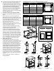
2. Remove Door
Withdrillorscrewdriver,removedoorhingesfromcabinetanddoor.
IMPORTANT:DoormustberemovedpriortoWasteBinChassisinstallation.
3. Install Waste Bin Chassis
Lower and insert rear of chassis so that the channels on the chassis fit
ontotheslidesontheslidingbaseassembly.Pushchassistowardthe
backofthecabinetuntilitsitsagainstthebackoftheslidesandyou
heara"click".Thechassisisnowfullyseatedandlocked.Graspthe
doormountbrackets,slowlypullthechassisoutofthecabinetuntilit
stopsmoving.Bothslidesshouldfullyextend.NOTE:Ifyourslidesdo
not fully extend, your chassis is not seated properly. To correct, push
thedrawerslideforwarduntilitlocksintoposition.
4. Determine Door Bracket Position
4A. Measure the door width by measuring from the outside edge of the left
door stile to the outside edge of the right door stile. Then, determine the
center door panel width by measuring from the inside edge of the left
door stile to the inside edge of the right door stile. These two measurements
determinethedoorbracketmountingarea.Locateyourproductassembly
onthechartsthatfollow.SelecttheOutsidetoOutsideEdgeofBrackets
(Z)measurementthatfitswithinyourdoorbracketmountingarea.This
determinesifyourBracketsFaceOutwardorInward,asshownonchart.
Ifyourdoorbracketsfaceinward,gotostep5.
NOTE:AllUSC18-2-50unitdoorbracketsfaceoutward.USC18-2-50
unitispre-assembledwithdoorbracketsoutward.SkiptoStep5.
A
E
F
B
C D
G
2
3
1B
1-1/4"
(3.2 cm)
1A
DO NOT
OVER
TIGHTEN
Template