® Education TEACHER’S GUIDE LEVERS AND PULLEYS UNDERSTANDING MECHANISMS 78610
Levers�and�Pulleys�Teacher’s�Guide 96562-V3-10/14 © 2014 K’NEX Limited Partnership Group and its licensors. Text: Dr. Alex Wright, AW Education, Wrexham, LL12 7LR, U.K. K’NEX Limited Partnership Group P.O. Box 700 Hatfield, PA 19440-0700 Visit our website at www.knexeducation.co.uk or www.knexeducation.com K’NEX Education is a Registered Trademark of K’NEX Limited Partnership Group. Conforms to the Requirements of ASTM Standard Consumer Safety Specification on Toy Safety, F963-03. Manufactured under U.S.
2
Your K’NEX Levers and Pulleys kit is part of a series called “Understanding Mechanisms”. The series has been produced to enable Key Stage 2 pupils to investigate and evaluate some familiar products, to think about how they work and to explore the mechanisms that make them work. • A glossary of technical terms and scientific definitions is offered as a resource for the teacher.
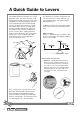
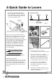
A�Quick�Guide�to�Levers It is thought that levers have been in use since prehistoric times. They were most likely used to help people lift and move heavy rocks in the Palaeolithic era, to build megalithic structures such as Stonehenge in the Neolithic period, and were the basis of the balances used by early traders and merchants to weigh gold and other valuable trade goods. Today they are found in many commonly used devices such as scissors, pliers, stapling machines, tweezers, and nutcrackers.
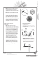
Effort - the force you apply to the lever to move an object or to overcome a resistance. The effort can be a push, pull, squeeze or lift. • a Load - the mass of the object you need to move or the resistance to movement that must be overcome by the lever. This object provides the force that acts against the effort.
A�Quick�Guide�to�Levers • Increase the speed the load moves. This characteristic of a lever can be seen in the seige engines known as trebuchets that were used to throw large stones at castle walls in medieval times. 1st Class Levers Fig. 3 Fig. 2 Figure 2 shows a large medieval trebuchet a giant lever in which the fulcrum is off-centre. A massive effort is applied to move a small load.
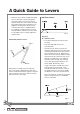
the effort x its distance from the fulcrum on one side = A Quick Guide to Levers The Principle of Levers identifies a relationship between the effort, the load and the distance of each from the fulcrum. This principle states that a lever is balanced (or in a state of equilibrium) when: the load x its distance from the fulcrum on the opposite side 2nd Class Levers Fig. 4 A pair of scissors is an example of two 1st Class levers working together.
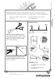
A�Quick�Guide�to�Levers • 2nd Class levers always amplify the output force. In this type of lever arrangement, the load is always closer to the fulcrum than the effort force. This means the effort arm will be longer than the load arm (see diagram). The longer the effort arm, the more the effort force is amplified where it is needed, so making it easier to move the load. With a 2nd Class lever, therefore, it is possible to move a large load with a smaller effort.
A Quick Guide to Levers Compound 3rd Class levers A small movement of the fingers squeezing the two arms together produces a long movement at the tips of the tweezers in order to grip an object such as a hair. The load is the resistance of the hair. Some machines use more than one type of lever in their working mechanisms. For example, raising a fish with a fishing rod actually requires more effort force than just lifting the fish using only a handheld line.
A�Quick�Guide�to�Levers JCB excavators that use a series of hydraulically operated arms are good examples of multiple levers in action. The main boom is a 3rd class lever. The excavating arm is a 1st class lever. Useful Web Sites. Effort Fulcrum Load The excavating arm is hinged onto the main boom and is pulled and pushed by the hydraulic cylinder attached to the main boom. The arm and bucket operating mechanism are examples of 1st class levers in action. http://www.enchantedlearning.
Lesson 1: Getting Started Lesson�1:�Getting�Started Time: 1 hour NOTE: This lesson, which introduces children to the K’NEX materials and building techniques, is included in each of the Understanding Mechanisms Teacher’s Guides. If your class is already familiar with the K’NEX Understanding Mechanisms kits you may omit it and begin with Lesson 2.
• Ask the children to: • Make a tall, stable structure. • Make a model with moving parts. • Ask the children to make drawings of their models and to label them showing: • How and where they made the structure stable. • How their model works and the movements the model makes.
Lesson 2: The Seesaw Lesson�2.1�and�2.2:�The�Seesaw 1st Class Lever Time for each lesson: 1.5 hours Note: Lesson 2.1 is appropriate for Key Stage 1 and as an introductory activity for Key Stage 2 children. Lesson 2.2 is more appropriate for Key Stage 2.
Lesson�2.1�and�2.2:�The�Seesaw� Whole Class • Ask the children to talk about the types of moving equipment they can find in playgrounds. • Encourage the children to describe the types of movement each piece makes. Answers may include: up/down; back and forward; swing; rocking; round and round/rotates/circle.
Lesson 2: The Seesaw model to identify the key parts of a lever - simply a rigid beam or rod that turns /rotates/ pivots about a point. • Help the children to understand that we even have levers in our own bodies – our arms and legs are levers. • Talk about how levers are probably one of the oldest machines known – perhaps used by people in prehistoric times to move large rocks or to help get mammoths out of pit traps.
Lesson�2.1�and�2.2:�The�Seesaw Working in Groups of 2-3 • Ask each group to prepare stickers and label their seesaw model. F - Fulcrum L – Load E – Effort Each group will need 2 paper cups (or pieces of foil) and some weights (paper clips/coins/standard weights). 1. Feel the load: • Ask one child from each group to place the back of their hand and arm on the desktop.
Talk about how levers can be found everywhere, but they do not all look like seesaws. Other examples of levers include scissors to cut paper, a claw hammer to pull a nail out of piece of wood, a stapler, an oar used to row a boat and even their own arms and legs. Extension Activity 1 Some children may feel it was easier to move the paper cup using the lever than without it. Discuss how they might be able to carry out a fair test to verify their ideas.
Lesson�2.1�and�2.2:�The�Seesaw • Try it and see. Were their predictions correct? • Ask the children to use written text to describe and explain their observations. They should include labelled drawings of their model with arrows to indicate movements and they should use the correct terminology to describe the different components. Teacher’s Notes The children should find that it requires a much smaller effort (a push or weighted paper cup) to lift the load.
Ask the children if they think it will be harder to lift the load when it is placed a long distance from the fulcrum. Explain that they can reverse the load and effort ends of their seesaw lever model. Reposition the labelling stickers to the new arrangement and repeat the activities as before. • Ask the children to describe and explain their observations.
Lesson�3:�The�Balance� 1st Class Lever Time for each lesson: 1 - 1.
Teacher’s Notes If the load is not balanced evenly, one side will hang down lower than the other and make it difficult to carry. Working in Groups of 2-3 • Explain how the class will discover how a balance works by building and investigating a K’NEX model balance. • Lesson 3: The Balance • Ask them why it might be easier for him to carry loads in this way.
Lesson�3:�The�Balance balance arm will move in the direction of the larger force. This is a general law of physics. Teacher’s Notes If time allows you may wish to demonstrate other examples of objects that remain stationary and have clearly identifiable and familiar forces acting on them. For example, an object suspended from a string, thread or elastic band will remain in that position.
Teacher’s Notes The children should note that the heavier tray goes down while the lighter tray moves up. They should also report that this is the result of unbalanced forces in action. • Pose the question, “What do you have to do to balance the forces in the model?” The children may either add, or remove, a grey pulley to one or the other side in order to make the weights on both sides equal. The children should be encouraged to discuss their observations in terms of balanced and unbalanced forces.
Lesson�3:�The�Balance Using a template: Younger children might use squared graph paper to record and visualise their results. For example: The children measure the relative distance they placed the grey K’NEX pulley hangers, the number of washers or paperclips or the value of the masses used to balance their model, in the appropriate distance measurement, as measured from the fulcrum. The blue connecting Rod on the hangers could be placed through the washers or paper clips to prevent them falling off.
Discuss the results of their investigation in which they explored balancing the forces acting on the model. They should have found that when balanced, the forces on one side must equal the forces on the opposite side. Teacher’s Notes To promote the wider use and application of ICT skills and practices, the children’s models and work might be recorded using a digital camera.
Lesson�4:�The�Wheelbarrow� 2nd Class Lever Time: 1 - 1.
Lesson 4: The Wheelbarrow Whole class • Review how, in previous lessons, the children investigated the type of lever used in a seesaw and a balance. Explain that in this lesson they will investigate a different type of lever and discover how it operates in a wheelbarrow. Children may be familiar with a wheelbarrow but they may not recognise it as a lever in action. Working in Groups of 2-3 • Ask each group to build their K’NEX wheelbarrow model and investigate how it works.
Lesson�4:�The�Wheelbarrow� 2nd Class Lever Teacher’s Notes The wheelbarrow, although a lever in action, is a different type of lever from that found in the balance and seesaw. In those simple machines the fulcrum is between the effort and load. Talk about how both types of levers share the same features – a rigid beam that rotates about a fulcrum, effort and load. See the ‘A Quick Guide to Levers’ for additional information.
Lesson 4: The Wheelbarrow Extension Activity 2 The wheelbarrow without a wheel If time is available, or during an ICT lesson, children could use the Internet to research the “travois”. Not all cultures used the wheel to help move heavy loads. Many nomadic peoples used a different method, similar in principle to the wheelbarrow, but without the wheel. For example, Native Americans on the Great Plains used the ‘travois” to move their household belongings.
Lesson�5:�The�Ice�Hockey�Stick� 3rd Class Lever Time: 1 - 1.
Lesson 5: The Ice Hockey Stick • Introduce the activity by telling the children the ice hockey player in the photograph on Page 8 of the K’NEX Building Instructions needs an improved design for his hockey stick to help him score more goals. He knows that he isn’t hitting the puck fast enough but he is not sure whether he needs to buy a longer or a shorter hockey stick. The children’s task is to provide evidence to help him make his decision.
Lesson�5:�The�Ice�Hockey�Stick • Their partner marks the start and stop lines and measures the distances moved by the head of the hockey stick and their partner’s hand. • Their wrist movement is essentially the same as a door opening on a hinge. • Ask each group to use dot stickers or masking tape to label the positions of the fulcrum (F), load (L) and effort (E) as well as the direction of the forces involved (using arrows) on their model.
Ask the children to describe and explain their observations. To demonstrate how a hockey stick works they should use labelled drawings, which include the positions of the fulcrum, effort and load as well as the direction of the forces that are applied.
Lesson�5:�The�Ice�Hockey�Stick Extension Activity 1 • Ask the children to investigate other 3rd Class levers used in sports, such as cricket bats, golf clubs, baseball/softball bats, tennis racquets, and fishing rods. Provide examples of these pieces of equipment for the children to examine.
Lesson 6: The Scissors Lesson�6:�Scissors Connected 1st Class Levers Time: 1 - 1.
Lesson�6:�Scissors Teacher’s Notes Use a magnifying glass to show children the shape of the cutting edge. The role of the levers is to amplify the squeezing forces from your hand. Cutting edges of scissors. See K’NEX Introducing Mechanisms: Wheels and Axles and Inclined Planes Teacher’s Guide for further work on wedges. The blades cut with great force into the paper and, just like all wedges, move the cut paper edges apart in a sideways direction.
You may find it useful to draw a diagram on the board to illustrate this arrangement. • Ask each group how they might test the scissors’ cutting action? Fingers are NOT allowed, even with plastic. • Where is the strongest cutting action found? • Where is the weakest cutting action found? • Ask the children to describe and explain verbally and in written text, how their K’NEX scissors work.
Lesson�6:�Scissors� Design Task Ask the children to modify the design of their K’NEX scissors model so that it has a much stronger cutting or gripping action. With the aid of a labelled drawing of their design, they should write a description of how their design works and state how their modifications have made the cutting action stronger. They should also include the results of any tests they carried out.
A pulley is a very simple type of mechanism; it has been used for thousands of years to make easier the job of lifting heavy objects. The simplest type of pulley mechanism is a single pulley. When a single pulley is used as a lifting device, the effort force needed to raise the load must be equal to or just greater than the load. In theory the effort needed to lift the load is the same as if the load was lifted directly from the ground without using a pulley.
A�Quick�Guide�to�Pulleys 2. Pulleys can also be used to move loads horizontally using a vertically applied effort force. A downward pull on a rope attached to a pulley system, can move a clothesline horizontally. • Sailboats and yachts make much use of these types of pulley systems to handle and control large heavy sails.
Single or fixed pulley Examples: flagpole, clothesline, painter’s platform. A single fixed pulley must be attached to a frame and the pulley wheel can rotate freely to reduce friction. Fixed pulleys change the direction of the applied effort force. The load moves the same distance as the effort force.
A�Quick�Guide�to�Pulleys In the example shown in Fig. 2, two pulleys are used. The weight of the load being raised is distributed equally between the two parts of the rope on either side of the movable pulley. The force needed to hold the system in balance or to raise it is now only half that of the load. The downside is that the effort force must move twice as far as the load. For example, to lift a 20N load a height of 3cm. the 10N effort force must move a distance of 6cm.
Lesson 7: The Flagpole Lesson�7:�The�Flagpole A Fixed Pulley System Time: 1 - 1.
Lesson�7:�The�Flagpole Working in Groups of 2-3 • Ask the children to build the K’NEX Flagpole model, (Pages 10-11 of the Building Instructions booklet), and allow them time to investigate how it works and what it does. • With the help of a labelled diagram drawn on the board, discuss how a pulley wheel works and how the rope fits into the groove in the rim of the wheel. Teacher’s Notes The children should not cut the string in this model.
* lifting heavy objects, as in cranes or running a flag up a flagpole. * Amplifying forces to help lift heavy objects using little effort. * transferring movement and forces in sewing machines and vacuum cleaners. * The circular motion of a motor is transferred to wheels or cylinders. * moving equipment in the gym or even opening and closing curtains. * Changing the direction of movement.
Lesson�7:�The�Flagpole • How might the children measure the forces needed? Step 3: Ask the children to repeat Step 2 but only this time they should measure the distances moved by their hand (the effort) when pulling on the string and the distance moved by the mass (the load). One child should grip the string just below the pulley and pull down slowly to lift the load.
Lesson 7: The Flagpole Extension Activity 1 Working in Groups of 2-3 • Ask the children to design a flag for their flagpole using coloured paper or cloth, felt-tipped pens or crayons. • How are they going to attach their flag to the string so that it is also easy to remove? • How can they make sure the flag can open in a breeze? OR Alternative activity Working in Groups of 2-3 Design a flag code message system to be used to send and receive short secret messages to and from another group.
Lesson�8:�The�Sailboat�� A Compound Pulley System Time: 1 - 1.
Lesson 8: The Sailboat • Ask the children to look at the pictures of different sailing boats. Talk about how, regardless of the size of the sailboat, sailors have always been faced with the same problem: how to lower and raise heavy sails safely. In days of large sailing ships sailors had to climb the masts and literally pull up large, heavy sails by hand – it was very dangerous work.
Lesson�8:�The�Sailboat Teacher’s Notes The distance moved by the effort or pulling force - the child’s hand pulling the string – is twice that moved by the load but the pulling force needed to move the load is halved. This is the trade-off. The pulling force (effort) needed is halved but the distance it has to move is doubled. • Ask the children to consider how the lower pulley differs from the pulley wheels at the top of the mast. Talk about the concept of movable pulleys.
Lesson 8: The Sailboat Extension Activity 1 Working in Groups of 2-3 If time is available, ask the children to design a sail for their sailboat using appropriate materials. The children could use photographs of sailboats to research ideas for sail designs and shapes.
Lesson�9:�The�Block�and�Tackle� A Compound Pulley System Time: 1 - 1.
• Before building their K’NEX Block and Tackle model ask the children to look at the plans for their model on Page 15 of the Building Instructions booklet. • Explain how the block and tackle is constructed by winding the rope around a number of fixed and movable pulley wheels. Teacher’s Notes The correct answer is 4 times. The multiplication can be found by counting the number of lengths of rope supporting the movable pulleys.
Lesson�9:�The�Block�and�Tackle� Investigating Further • Explain that as they use the block and tackle model to lift a load the children should try to discover answers to the following questions: • What did they find out about the amount of effort needed to lift the load? In cranes the counterweight is very heavy because it must be placed close to the fulcrum. Ask the children to identify the positions of the counterweights in the photographs of cranes they have found.
• How does lifting the weighted paper cup with the block and tackle compare to lifting it directly by hand? • Count the number of strings supporting the lower movable pulleys. What might this information tell you about how much this block and tackle system helps you to lift the load? • Using the block and tackle, raise the cup about 5cm.
Lesson�9:�The�Block�and�Tackle� Plenary Discuss what the children have learnt in the lesson using the words relating to the science and technology they discovered. Ask them what they think the effect of adding more pulleys to their block and tackle might be on its lifting ability. Talk about patterns that may be arising in their results from this and other lessons.
This list of key terms is intended as background information. While we recognize that some of these terms are not fundamental to National Curriculum requirements for Key Stage 2 Design and Technology and Science, we have nevertheless included them here to help you better understand some of the concepts investigated in the K’NEX Understanding Mechanisms kits. Key Terms and Scientific Definitions Key�Technical�Terms�� and�Scientific�Definitions SIMPLE MACHINE A simple tool used to make jobs easier to do.
Key�Technical�Terms�� and�Scientific�Definitions Work = Force x Distance moved by the object in the direction of the force or W=Fxd If the force is measured in newtons (symbol N) and the distance is in metres (m) then the work done (W) is measured in newton metres (Nm). The SI unit of work is the joule (J) and 1 joule = 1 newton metre. FORCE A force is a push or a pull which, when applied to an object, can make it change shape, move faster or slower, or change direction.
The calculation used is: Key Terms and Scientific Definitions MECHANICAL ADVANTAGE Most machines are designed to make jobs easier to do. For example, a wheelbarrow that allows you to move a heavy load of soil or a winch used to lift a heavy object. When a machine enables you to use a small effort to move a large load, that machine has given you a “mechanical advantage” you would not otherwise have had.
Key�Technical�Terms�� and�Scientific�Definitions TYPES OF MOTION 4 basic forms of motion are used in mechanisms: • Rotary: This can be seen in the movement of car, bicycle and gear wheels and in Ferris wheels or carousels as they go round and round on an axis. It is the most commonly occurring type of motion in a mechanism. • Oscillating: This is an alternating, or swinging to and fro, type of motion.
• Fixed Pulley: A pulley attached to a solid surface; it does not move when the rope is pulled, other than to turn in place. Fixed pulleys change the direction of an applied force. • Movable Pulleys: A pulley attached directly to the load being lifted; it moves when the rope is pulled. • Combination Pulleys: A series of fixed and movable pulleys used together to gain the advantages of both in doing the work.