® Education TEACHER’S GUIDE GEARS UNDERSTANDING MECHANISMS 78630
Gears�Teacher’s�Guide 96566-V3-10/14 © 2014 K’NEX Limited Partnership Group and its licensors. Text: Dr. Alex Wright, AW Education, Wrexham, LL12 7LR, U.K. K’NEX Limited Partnership Group P.O. Box 700 Hatfield, PA 19440-0700 Visit our website at www.knexeducation.co.uk or www.knexeducation.com K’NEX Education is a Registered Trademark of K’NEX Limited Partnership Group. Conforms to the Requirements of ASTM Standard Consumer Safety Specification on Toy Safety, F963-03. Manufactured under U.S.
2
Your K’NEX Gears kit is part of a series of called “Understanding Mechanisms.” The series has been produced to enable Key Stage 2 pupils to investigate and evaluate some familiar products, to think about how they work, and to explore the mechanisms that make them work.
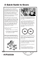
A�Quick�Guide�to�Gears You may claim to know very little about gears and gearing, but if you drive a car or have ridden a bicycle, then you know how to use them. When driving off from a stationary position do you choose a low gear or a high gear? What is likely to happen if you try to use the highest gear in this situation? Experience tells you that your car engine will stall if you try to move off from a stationary position using the highest gear.
Gears can also be connected using chain links – as in a bicycle. Gears used with chains are called sprockets. Sprockets do not mesh with other gear wheels but with the links in the chain. When moved, they turn in the same direction. As with spur gears, different sized sprocket gears turn at different speeds and with different amounts of force. If they are the same size, they turn at the same speed and with the same force. Crown gears are used to change the direction of rotary motion through 90-degrees.
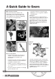
A�Quick�Guide�to�Gears What are gears used for? Gears are used in most machines with moving parts, from clocks and cars to egg whisks, lifting winches and hand drills. They come in different sizes and forms depending on the job they are designed to do. • Change the direction of motion through 90-degrees, as in an egg whisk, windmill and waterwheel. Gear basics The K’NEX Crank Fan model mechanism has the simplest gear arrangement, with two meshed gears of equal size.
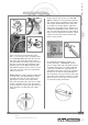
How can you make the driver and the follower gears rotate in the same direction? Add an idler gear between them. The addition of the idler gear will create an odd number of gears in the gear train and make the gears on either side rotate in the same direction. Input A Quick Guide to Gears Output Idler Gear Driver Gear Follower/Driven Gear The number of turns, or the force, you apply to the driver is the input movement or force; what is produced by the follower is the output movement or force.
A�Quick�Guide�to�Gears The small driver gear B must turn a number of times for the larger follower gear A to make one complete rotation or turn. This gear arrangement produces a slow output speed. The term used to describe this mechanism is gearing down. One of the important advantages of gearing down is to increase (amplify) the output turning force available. Try this! Ask someone to try to stop you turning the handle of the Crank Fan by holding onto the fan or output axle.
This is exactly the same situation as trying to ride a bicycle up a hill in a high gear or trying to start to drive your car by engaging a high gear (4th or 5th gear, for example) - the bike and the engine will stall. Key facts about speeding up • A large driver gear turning a small follower gear increases the output speed but decreases the turning forces on the output axle. • The mechanism by which this is achieved is called gearing up.
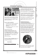
A�Quick�Guide�to�Gears This drawing represents a crown gear wheel used to change direction of movement through 90-degrees. This type of gear is called a crown gear – when looked at from the side it looks rather like a crown. The mechanism is called a crown gear wheel and pinion. The pinion is simply another name for a follower gear. Crown gears can be used in the same way as spur gears for gearing down, as in the K’NEX Phonograph model, and for gearing up, as in K’NEX Eggbeater model.
A Quick Guide to Gears Key facts about chain and sprocket systems: Chain drive systems use a chain and sprocket to transfer motion from the driver axle to the follower axle. The same rules apply to both simple gear trains and chain and sprocket systems: • With two sprockets the same size the input speed is the same as the output speed. • A small driver sprocket makes a large follower sprocket turn slowly but increases the turning forces on the output axle.
A�Quick�Guide�to�Gears Children may be encouraged to think about and discuss what they are doing through facilitating questions such as: • What does the machine do? • What are the functions of the moving parts? • How are the moving parts connected? How do they make other parts move? • What are the moving parts called? • What types of movements do the moving parts make? For example, the simple gear train used in the K’NEX Crank Fan model could be represented by the use of symbols and careful labellin
Useful Internet Web Sites www.coe.uh.edu/archive/ The University of Houston archive of lessons. Search >Collections > Science >Lesson plans >Simple Machines. A Quick Guide to Gears Some children, however, may want to produce more realistic drawings, such as this one showing the arrangement of a crown gear, or use photographs, taken with a digital camera, to record their observations. www.flying-pig.co.uk A general site for simple machines.
Lesson�1:�Getting�Started Time: 1 hour NOTE: This lesson, which introduces children to the K’NEX materials and building techniques, is included in each of the Understanding Mechanisms Teacher’s Guides. If your class is already familiar with the K’NEX Understanding Mechanisms kits you may omit it and begin with Lesson 2.
• Ask the children to: • Make a tall, stable structure. • Make a model with moving parts. • Ask the children to make drawings of their models and to label them showing: • How and where they made the structure stable. • How their model works and the movements the model makes.
Lesson�2:�The�Crank�Fan How to transfer rotary motion using a simple gear train Time: 1 hour + 1.5 hours The crank fan lesson is in two parts; the first part can be used with Key Stage 1 children using a limited vocabulary while both parts allow Key Stage 2 children to progressively investigate how gears work using a more expansive terminology.
* What does the machine do? * What happens when they turn the handle? Teacher’s Notes * Answers will vary but expect them to respond that the fan blades turn.
Lesson�2:�The�Crank�Fan direction(s) in which the gears move. The children should lay the gears on a piece of paper on their desk so that they mesh. Suggest that one child insert a pencil point into the central hole of each gear to hold them in place, while the other child turns ONE gear. • Ask them to notice what happens. • Do both gears move? • Do both gears move in the same direction? • Encourage them to add arrows to the gears to show the direction of movement.
• Other facilitating questions to ask the children might include: * What are the names of the parts that make the fan/lifting device turn/rotate? * What is the mechanism, used to turn the fan/ lifting device, called? * How would they make the fan/lifting device turn faster/slower? * Describe the type of movement made by the fan/lifting device? * What is the direction of movement made by the handle and fan? * Do the two gear wheels turn in the same d
Lesson�2:�The�Crank�Fan happens when they turn the handle slowly through one complete turn. The stickers will rotate in opposite directions and will come together again in time with the handle and fan. Whole Class • Talk about the children’s observations. Encourage them to use their K’NEX models to demonstrate their explanations through the use of correct technical vocabulary.
Teacher’s Notes Use caution when displaying the dismantled electric fan. Children should not touch the parts. Children could be encouraged to think about and discuss what they are investigating through the use of facilitating questions, such as: Lesson 2: The Crank Fan Whole Class Demonstrate how an electric fan works. It may be useful to have a partly dismantled electric fan on display. Use the K’NEX Crank Fan model to show how that fan works.
Lesson�2:�The�Crank�Fan Axle or shaft A,B Letter helps to identify gear being referred to in written descriptions B Follower 34 teeth Where gears mesh A Driver 34 teeth develop the children’s observational skills by focusing their attention on the way in which the machine works. Ask, for example, how the moving parts connect to each other. Their drawings should reflect these connections.
Whole Class Discuss the effect of changing the size of the driver and follower gear wheels. What other mechanisms can produce the same effect? Ask those children who have bicycles with gears what they do when they want to go faster. They change into a higher gear: the chain connects the large “gear wheel” attached to the pedals to the smallest gear on the back wheel.
Lesson�2:�The�Crank�Fan * The driver is larger than the follower. * The smaller follower gear wheel turns faster than the driver. * The driver is smaller than the follower. * The larger follower gear wheel turns more slowly than the driver. • They should use arrows to show the direction of movement. Teacher’s Notes If available, a digital camera could be used to record children’s models and be included with other ICT applications when creating reports.
Lesson 2: The Crank Fan • The gear ratio 1:6 indicates that for every one turn of the driver gear, six turns are produced by the follower gear wheel. Or, said another way, the output speed is six times faster than the input speed. This is called gearing up. • On the other hand, if a 14-toothed driver turns an 84 toothed follower gear we obtain a gear ratio of 84/14 or 6:1. • This gear ratio indicates that the output will be 6 times slower than the input speed.
Lesson�3:�The�Car�Window How to convert rotary motion into linear motion Time: 1 hour Learning Objectives - Children should learn: • to investigate and disassemble products in order to learn how they work • how to convert rotary motion into linear motion • to communicate information about products and mechanisms through labelled drawings Possible Teaching and Learning Activities Whole Class Introduction Children are familiar with the action of opening and closing car windows - they turn a handle or
Lesson 3: The Car Window Possible Teaching and Learning Activities Ask the children to talk about other examples of lifting and lowering mechanisms with which they may be familiar or which they have investigated in previous lessons. These may include: QCA DfEE Exemplar Scheme of Work for Design & Technology Units: 1A Moving Pictures; 2C Winding Up; 4B Story Books; 5C Moving Toys.
Lesson�3:�The�Car�Window * Why a small gear wheel is used as the driver to turn a large follower. * How they can control the speed of the output movement. Teacher’s Notes * To slow the movement of the window and to increase the output force. * Turn the handle faster. * Why the handle turns many times but the window only rises very slowly. * * Whether or not the mechanism will be easier to turn without the handle.
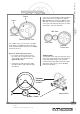
Follower / Driven gear: 34 teeth A B Driver: 14 teeth Gear Train 2 Follower / Driven gear: 82 teeth A B Driver: 14 teeth Lesson 3: The Car Window Gear Train 1 This slowing is called gearing down. In the first gear train, a small (tan) driver gear (14-teeth) drives a larger (yellow) follower gear (34teeth), while in the second gear train another 14-tooth gear drives a large 82-toothed gear. This twofold slowing down process causes the large 82-toothed gear to move very slowly.
Lesson�3:�The�Car�Window window arm moves up and down. The movement of the arm raises and lowers the window. Notice how the vertical part of the window raising mechanism always stays vertical. Its motion is linear while the handle and gears rotate. This mechanism is an example of a linkage. A linkage is an important control system because it allows forces and movements to be transferred. It also changes the direction of a force or makes things move in a particular way.
How to change the direction of rotary motion through 90-degrees Time: 1 hour Learning Objectives - Children should learn: • to investigate and disassemble products in order to learn how they work • how to change the direction of rotary motion through 90-degrees • to communicate information about products and mechanisms through labelled drawings.
Lesson�4:�Blender • How some blenders use different speed settings in order to chop, beat or homogenize the food. • Explain to the children how they will investigate one possible mechanism to operate the cutting blades of a blender. Their blender will be hand operated.
* Identify and describe the parts that move and explain what they do. Teacher’s Notes * Gear wheels move. They transfer rotary movement and force. * Identify the parts that move in a vertical plane and those that move in a horizontal plane. * Crank: vertical; 1st gear: vertical; 2nd gear: horizontal; blades: vertical.
Lesson�4:�Blender Whole Class • Using a K’NEX Blender model, demonstrate and introduce/reinforce the vocabulary the children should use when describing the working of their model. For example: input and output, mechanism, driver, follower and crown gear wheel mechanism. • Explain to the children that they have been exploring a crown gear system. This gear system is used to change the direction of motion.
Teacher’s Notes To promote the wider use and application of ICT skills and practices, the children’s models and work might be recorded using a digital camera. Lesson 4: Blender Working in Groups of 2-3 Ask the children to record their observations and results using labelled drawings and notes. They should employ the correct vocabulary and terminology to show how the mechanism works. Their drawings should have arrows to show the direction of movement.
Lesson�5:�The�Stationary�Exercise�Bicycle How to transfer motion and forces using a chain and sprocket mechanism Time: 1 - 1.
If possible, provide an example of an exercise bike (you could use the K’NEX model) or a bicycle for the children to investigate. Alternatively, ask the children to look at the photograph on Page 12 of the Building Instructions booklet to interpret how they think the mechanism works.
Lesson�5:�The�Stationary�Exercise�Bicycle • With the model as an example, demonstrate on the board how to make simple labelled drawings, using arrows to show the direction of movement. The diagram below, for example, could be used as a symbolic representation of a chain and sprocket drive system. The chain and sprocket drive system uses a chain to transmit rotary motion from a driver axle to a follower or driven axle. Sprockets are toothed wheels on which a chain runs.
* Whole Class • Discuss how the pedals on a bicycle are similar to the handle (crank) in a winding mechanism and in the other K’NEX models they have made, such as the crank fan, blender and record player. Teacher’s Notes Bicycle pedals are another example of a crank, identical in practice to the handle operating the K’NEX Crank Fan model. Cranks work as if they are rotating levers. Remember that long levers allow you to create large turning forces.
Lesson�5:�The�Stationary�Exercise�Bicycle • Ask for volunteers, taking turns, to summarize the way in which motion is transferred through the station ary bike system. The first volunteer should start the description at the pedals and the last volunteer describes what happens at the rear wheel. Teacher’s Notes Turning the pedals transfers motion and energy through the driver axle to the sprocket at the front of the bike (driver sprocket).
This list of key terms is intended as background information. While we recognize that some of these terms are not fundamental to National Curriculum requirements for Key Stage 2 Design and Technology and Science, we have nevertheless included them here to help you better understand some of the concepts investigated in the K’NEX Understanding Mechanisms kits. Key Terms and Scientific Definitions Key�Technical�Terms�� and�Scientific�Definitions SIMPLE MACHINE A simple tool used to make jobs easier to do.
Key�Technical�Terms�� and�Scientific�Definitions Work = Force x Distance moved by the object in the direction of the force or W=Fxd If the force is measured in newtons (symbol N) and the distance is in metres (m) then the work done (W) is measured in newton metres (Nm). The SI unit of work is the joule (J) and 1 joule = 1 newton metre. FORCE A force is a push or a pull which, when applied to an object, can make it change shape, move faster or slower, or change direction.
The calculation used is: Key Terms and Scientific Definitions MECHANICAL ADVANTAGE Most machines are designed to make jobs easier to do. For example, a wheelbarrow that allows you to move a heavy load of soil or a winch used to lift a heavy object. When a machine enables you to use a small effort to move a large load, that machine has given you a “mechanical advantage” you would not otherwise have had.
Key�Technical�Terms�� and�Scientific�Definitions TYPES OF MOTION 4 basic forms of motion are used in mechanisms: • Rotary: This can be seen in the movement of car, bicycle and gear wheels and in Ferris wheels or carousels as they go round and round on an axis. It is the most commonly occurring type of motion in a mechanism. • Oscillating: This is an alternating, or swinging to and fro, type of motion.
• Fixed Pulley: A pulley attached to a solid surface; it does not move when the rope is pulled, other than to turn in place. Fixed pulleys change the direction of an applied force. • Movable Pulleys: A pulley attached directly to the load being lifted; it moves when the rope is pulled. • Combination Pulleys: A series of fixed and movable pulleys used together to gain the advantages of both in doing the work.
Gears: Changing direction, speed, and force... A gear is a wheel with teeth along its outer rim. Gears can: • Change the DIRECTION in which something moves. • Change the SPEED at which something moves. • Change the FORCE needed to make something move.
Gears: On the move Driver Gear Follower/Driven Gear DRIVER GEAR: The gear to which the effort force is applied. FOLLOWER/DRIVEN GEAR: The gear connected (meshed) to the driver gear.
GEAR TRAINS: Changing the direction of rotation… Idler Gear Driver Gear Follower/ DrivenGear Two or more gears meshed together make up a gear train. Meshed gears turn in opposite directions. An idler gear makes the gears on either side of it turn in the same direction.
CROWN GEARS: Changing planes… A crown gear meshes at right angles (90-degrees) to another gear and changes the direction of motion. One gear turns vertically (up and down), while the other turns horizontally (side to side).
GEAR TRAINS: Changing speed and force Small follower gear - (fast) output Large driver gear - (slow) input SPEEDING UP/GEARING UP: A large driver gear makes a small follower gear turn faster. This increases turning speed, but reduces turning force. Large follower gear - (slow) output Small driver gear - (fast) input SPEEDING DOWN/GEARING DOWN: A small driver gear makes a large follower gear turn more slowly. This reduces turning speed, but increases turning force.
GEARS: Try This ...