HT200 Users Manual v1.0 Complies with part 15 of the FCC rules. Operation is subject to: 1. This device may not cause harmful interference 2. This device must accept any interference received including interference that may cause undesired operation. WARNING: TO REDUCE THE RISK OF ELECTRIC SHOCK, DO NOT REMOVE THE COVER, NO USER SERVICEABLE PARTS INSIDE. REFER SERVICING TO QUALIFIED SERVICE PERSONNEL. WARNING: TO PREVENT FIRE OR SHOCK HAZARDS, DO NOT EXPOSE THIS PRODUCT TO RAIN OR MOISTURE.
IMPORTANT SAFEGUARDS These safety instructions are to ensure the long life of your projector and to prevent fire and shock. Please read them carefully and heed all warnings. Installation • For best results, use your projector in a darkened room. • Place the projector on a flat, level surface in a dry area away from dust and moisture or hang it from the ceiling with an approved mount kit. • Do not place your projector in direct sunlight, near heaters or heat radiating appliances.
Table of Contents 2 3 IMPORTANT SAFETY INFORMATION Table of contents 4 5 5 Basic information Features Remote control 6 7 8 9 10 11 13 13 Terminal connections Projector part identification Projector positioning Connecting video equipment Connecting component video Connecting a PC or Macintosh Using the remote control as a computer mouse Wireless mouse function 13 13 15 16 17 18 18 19 19 19 19 20 Using the projector Selecting the input source Turning the projector off Changing the computer’s video reso
Basic HT200 Information Congratulations On Your Purchase of the HT200 Projector! The HT200 is one of the very best Projectors available today. The HT200 enables you to project precise images up to 300 inches across (measured diagonally) from your PC or Macintosh computer (desktop or notebook), VCR, document camera, laser disc player, DVD player, etc. The Projector can be placed on a tabletop or cart, or permanently mounted on the ceiling. You may use the Projector to project images from behind the screen.
Remote Control Inserting the batteries 1) Press firmly and slide the battery cover off. 2) Insert the supplied two batteries (size AA/R6). Ensure that the polarities (+ and -_) of the batteries are aligned correctly. Always replace batteries with fresh alkaline type. 3) Slip the cover back over the batteries until it snaps into place. Notes • If the remote control gets wet, wipe it dry immediately. • Avoid excessive heat and humidity.
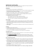
Terminal Connection Panel Projector Part Identification 6
Installation The distance from the projector lens to the screen determines to the size of the projected image, therefore, you need to consider the place where you set up the projector and screen before making connections. You also need to consider the screen size and height of the unit and screen as other important factors. Tip: Although not advised, a non-glossy wall may be used as a substitute for a screen.
Use the following information to position the projector. Horizontally the projector needs to be positions with the lens-centered left to right Projection Distance 4:3 Video Screen Distance to 47" 83" 122" Screen Screen Diag. 24" 40" 60" (min.) Screen Diag. 31" 53" 78" (max.) Projection Distance 16:9 Video Screen Distance to 47" 83" 122" Screen Screen Diag. 22" 36" 55" (min.) Screen Diag. 28" 48" 72" (max.) Projection Distance 1m = 39.
Connecting Video Equipment You can connect a document camera, VCR, laser disc player, and DVD player, etc. Connecting to the VIDEO IN VIDEO/S-VIDEO JACKS You can connect up to two pieces of video equipment to the VIDEO IN jacks following the illustration below. Two types of connections can be made. Connect either using the cables indicated in dotted lines or those in gray as shown in the drawing below.
Connecting Component Video Equipment withYCbCr output jacks to the RGB IN connector You can also connect the video component to the RGB IN connector, if the video component has the component video (YCbCr) signal jacks. This connection may provide a better picture quality than the connections on page 9. • You can switch the input source to VIDEO, S-VIDEO, or RGB. • The AUDIO IN jack is for equipment connected to the RGB IN connector. Before connecting • Turn off the components that are to be connected.
Connecting a PC or Macintosh Connecting a PC or Macintosh to the Projector enables computer images for impressive presentations. • The following display standards are supported: VGA 640x480 for graphics VGA 640x400 for graphics VGA 640x350 for graphics VGA 720x400 for text CGA 720x350 for text SuperVGA 800x600 Macintosh at 640x480 Macintosh at 832x624 • If your PC does not support XGA you will need to install a XGA graphics board. Consult your computer's owner's manual for your XGA configuration.
Modifying the DIP switch (for Macintosh) setting Modify the DIP switch setting on the MAC cable as shown below.
Connecting the remote mouse receiver to an IBM PC/AT computer Connect the IBM/Mac connector on the remote mouse receiver and PC's mouse port with the supplied serial cable. Connecting the remote mouse receiver to an IBM PS/2 or Macintosh computer Connect the supplied serial cable to the IBM/Mac connector on the remote mouse receiver. Connect the supplied mouse adapter to the other end of the serial cable and the computer mouse port.
2) Press the POWER ON button on the remote control or the POWER button on top of the unit to turn on the unit. The POWER indicator on top of the unit turns to green and start blinking. It will take one minute for the projector to be ready to use. Wait until the indicator stops blinking and lights steadily in green. Note: While the POWER indicator is blinking, the unit doesn't turn off even if you press the POWER OFF button on the remote control or the POWER button on the unit.
7) Change the unit setting to suit to the projecting method and selected source as described in step 4. • Select the type of projection If the projected image is horizontally reversed or upside down, change the projection type. See page 19. • If the component video signal output jacks of the video component are connected to the RGB IN connector (see page 10), set "INPUT MODE" to YCbCr" in the menu. This setting can provide a better picture image. See page 20.
Changing computer's video resolutions Depending on your computer's graphic capability, you may be able to select one of several resolutions. Generally a computer- either a PC or Macintosh- with 1 MB VRAM will run: 640 x 480 at 16.7 million colors (24 bit True color) 800 x 600 at 65,000 colors. 1024 x 768 at 256 colors. As the resolution increases, the number of colors you can run decreases. With 2 MB VRAM a computer will run: 640 x 480 at 16.7 million colors (24 bit True color). 800 x 600 at 16.
Adjusting the volume of the projector speaker Press VOLUME + to increase the volume or - to decrease. The volume can also be adjusted with the menu operation (see page 24). Using the laser pointer You can highlight the desired point on the screen with the beamed red light. ***Caution*** Do not look into the laser pointer while it is on. Do not point the laser beam at any other persons. This could result in serious eye damage or blindness. Press the LASER button.
Menu operation- Selecting the input source with the remote 1) Press MENU. The button lights in red and the main menu appears on the screen. If you don't proceed to step 2 within ten seconds, the button goes off. Note: The menu will not be displayed if the picture is enlarged even slightly. In such a case, reduce the picture size to normal before starting the menu operation. 2) Press the cursor up or down to select "SOURCE MENU." SOURCE MENU 3) Press L-CLICK.
of the selected menu item. value of the selected menu item. Selecting the projection type; Floor, Ceiling, Rear and Front This reorients your image for your type of projection. 1. Press MENU to display the main menu. 2. Press the cursor up or down key to select "SETTING MENU." 3. Press L-CLICK to display the SETTING MENU. 4. Press the cursor up or down key to select "PROJECTION." 5. Press the cursor +/- key to select the projection type, which suits the Projector setup conditions.
Setting "INPUT MODE" to "YCbCr" or Component Video When you have connected the component video (YCbCr) signal output jacks of the video component to the RGB IN connector on the unit (see page 10), set "IMAGE MODE" to "YCbCr" to obtain better picture quality. 1. Select the input source RGB (see page 13). 2. Press MENU to display the main menu. 3. Press the cursor up or down key to select "IMAGE ADJ MENU." 4. Press L-CLICK to display the IMAGE ADJ MENU. 5.
Timing Chart Signal Resolution H. Sync. (kHz) 15.734 15.625 15.625 37.86 35 31.47 37.86 31.47 31.47 31.47 34.97 35 37.86 37.5 39.375 43.269 39.44 31.469 31.469 37.927 39.375 35.16 37.879 48.077 46.88 53.674 49.725 48.363 57.476 58.131 60.241 60.023 V. Sync. (Hz) 59.94 50 50 85.08 66 70 85.08 59.94 60 60 66.67 66.67 72.81 75 75 85.01 87.85 70.09 70.09 85.04 87.7 56.25 60.32 72.19 75 85.06 74.55 60 70.07 72.03 74.93 75.03 Dot Clock (MHz) 31.5 30.24 25.175 31.5 25.175 25.175 25.175 31.334 30.24 31.5 31.
Adjusting the clock frequency (PICTURE ADJ) and clock phase (FINE PICTURE) manually When "AUTO PICTURE" is set to "ON," the clock frequency and clock phase will be adjusted automatically. However, if you need any manual adjustment for these two items, you first need to set "AUTO PICTURE" to "OFF" as indicated in the following steps. Adjust the clock frequency to eliminate any vertical banding, then clock phase to reduce any video noise, dot interference, or cross talk.
Storing the most recent “PICTURE ADJ,” “FINE PICTURE,” “H POSITION,” AND “V POSITION” settings You can store the above present settings in the memory. CUSTOM 1 to 5. 1. Select the input source RGB (see page 13). 2. Press MENU to display the main menu. 3. Press the cursor up or down key to select “SETTING MENU.” 4. Press L-CLICK to display the SETTING MENU. 5. Press the cursor up or down key to select “CUSTOM MEMORY.” 6. Press the cursor +/- key to select the memory CUSTOM 1 to 5. 7.
Adjusting the picture elements The picture elements such as brightness, contrast, white balance, and so on can be adjusted individually for each input source. The adjustable items vary depending on the input source and “INPUT MODE” setting (see page 20). Input source (The elements marked with “O” are adjustable.) BRIGHTNESS CONTRAST COLOR TINT SHARPNESS WHITE BALANCE VIDEO S-VIDEO RGB INPUT MODE (see page 24.) RGB YCbCr O O O O -O -O --O O O O O O O O 1. 2. 3. 4. 5.
The following three types of gamma modes can be selected according to your preferences: • NORMAL, • NATURAL 1, or • NATURAL 2. 8. Press L-CLICK. 9. Press the cursor up or down key to select “INPUT MODE,” then press the cursor +/- key to select the input mode. If the input source is RGB, refer to “Setting INPUT MODE to YcbCr” on page 20.
Turning the projector off with on screen functions With the remote control: Press the POWER OFF button a for 2 seconds (the projector will turn off regardless of the “POWER OFF” setting) With the projector keypad: (When “DISPLAY” is set to “ON”) Press the POWER button. “POWER OFF/ENTER” appears. Press ENTER. The projector will turn off. With the projector keypad: (When “DISPLAY” is set to “OFF”) Press the POWER button for 2 seconds. The projector will turn off.
Specifications Optical DMD TM Lens Lamp Image Size Projection Distance Light Output Contrast Ratio Color Temperature Single Chip Digital Micro Device (DMD TM), 800x600 dots Manual zoom, manual focus F3.0 f =27.5 to 35.75mm Metal halide lamp 280W 610 to 7620mm (24 to 300 inches) diagonal 1.2 to 12.3m 800 ANSI lumens (normally white) 500:1 7000 Kelvin Electrical Inputs Video (NTSC/PAL/SECAM/NTSC4.43) RGB (H:15 to 60 kHz, V:50 to 85 Hz) 60 MHz Full color, 16.7 million colors simultaneously.
Troubleshooting This section helps you resolve problems while setting up or using your projector. Common Problems & Solutions Problem Does not turn on No picture Check These Items Check that the cord is plugged in and that the power switch on the back panel is on. (See page 13.) Check the status light to see if the projector has overheated or the lamp usage exceeds 1100 hours. (See pages 29 and 30.) Use the menu icons to select your source (Video, SVideo, or RGB). (See page 13.
When the STATUS indicator on the projector keypad lights or blinks Status Light Message Condition OFF On Continually Blinking Very Rapidly (On and off in a cycle of 1 sec.) Blinking Rapidly (On and off in a cycle of 4 sec.) Status Normal The projector lamp has exceeded 1000 hours of operation and should be replaced. The lamp housing is not correctly installed. Install it correctly. The temperature protector has been triggered. If the room temperature is high, move the projector to a cool location.
Lamp housing replacement procedure 1. Switch off the main power and unplug the power cord. 2. Wait at least one hour for the lamp to cool. 3. Turn the unit upside down carefully. 4. Loosen the lamp cover securing screw. 5. Slide the lamp cover in the direction of the arrow and remove it. CAUTION: Do not use a lamp housing other than the Knoll replacement lamp housing. Order this from your Knoll dealer using your projector’s model number (see “Note” below). 6. Loosen the three lamp housing securing screws.