HD108 HD178 HD290 DLP™ Projector Users Manual v1.
FCC Warning Note: This equipment has been tested and found to comply with the limits for a Class B digital device, pursuant to part 15 of the FCC Rules. These limits are designed to provide reasonable protection against harmful interference in a residential installation. This equipment generates, uses and can radiate radio frequency energy and, if not installed and used in accordance with the instructions, may cause harmful interference to radio communications.
TABLE OF CONTENTS Safety Warnings Introduction Positioning the projector Choosing the aspect ratio 4 5 7 8 Video connectors Connecting a video device Composite (RCA) video connection S-video connection Component (RCA) connection SCART RGB connection 8 9 9 9 9 9 Digital connections DVI connection HDMI connection 10 10 10 Computer connections RS-232 connections (HD178 and HD290 only) 10 10 Displaying an image Adjusting the image Shutting down the projector 11 11 12 Troubleshooting your setup 12
Important Operating Considerations for Safety Place the projector in a horizontal position no greater than 15 degrees off axis. Locate the projector in a well-ventilated area without any obstructions to intake or exhaust vents. Do not place the projector on a tablecloth or other soft covering that may block the vents. Locate the projector at least 4' (1.2 m) away from any heating or cooling vents. Use only Knoll-approved ceiling mounts. Use only the power cord provided.
Introduction Congratulations and thank you for your excellent choice of a superior digital image projection device. Your new Knoll projector is specifically designed for home cinema applications. The projector sets a high standard using the latest DLP™ technology and new DNX video processing from Pixelworks™. Whether you are watching movies or High Definition broadcasts or playing the latest video game, you will enjoy amazing image quality.
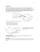
Component RCA S-Video Rear Connector Panel 12-volt DC output HDMI M1/DA/DVI Composite RCA RS-232 (not on HD108) The projector provides the following connection options: • M1-DA/DVI (Digital Visual Interface) • HDMI™ (High Definition Multimedia Interface) • Component (RCA) • SCART RGB (you must enable this connector, see page 9) • S-video • Composite video (RCA) See “Video connectors” on page 8 for details.
Setting up the Projector There are a number of factors to consider when determining where to set up the projector, including the size and shape of your screen, the location of your power outlets, and the distance between the projector and the rest of your equipment. But here are some general guidelines. NOTE: To ensure adequate cable access, do not place the projector within 6 inches (0.15 m) of a wall or other object. Position the projector on a flat surface at a right angle to the screen.
HD108 Projection Throw Distance 16:9 Video Screen: Screen Diagonal 92" 103" 106" 110" 122.5" 146.75" Minimum Distance 142" 158" 163" 169" 188" 225" Maximum Distance 170" 190" 195" 203" 226" 271" Screen offset 12.6" 14.1" 14.5" 15" 16.8" 20.7" Viewing Area 45"x80" 50.5"x89.75" 52"x92" 54"x96" 60"x107" 72"x128" MAXIMUM DISTANCE TO SCREEN (16:9) = 1.848 x SCREEN DIAGONAL SIZE MINIMUM DISTANCE TO SCREEN (16:9) = 1.
Video Connectors Component RCA S-Video 12-volt DC output HDMI M1/DA/DVI Composite RCA RS-232 (not on HD108) The first step for connecting video is determining what type of output connectors your video Component RCA device has. If there is more than one output, select the one with the highest quality. The best quality ranking, with 1 being the highest, is: 1. M1-DA/DVI or HDMI (both are digital inputs) 2. Component /SCART RGB video (RCAs) 3. S-video 4.
Composite (RCA) video connection Plug the composite video cable’s yellow connector into the video-out connector on the video device. Plug the other yellow connector into the yellow Composite connector on the projector. S-video connection If your video device uses a round, four-prong S-video connector, plug the S-video cable into the S-video connector on your video device and into the S-video connector on the projector.
Computer connections You can connect a computer’s VGA connector to the M1-DA/DVI input on the projector using an M1-A cable. RS-232 connections (HD178 and HD290 only) You can control the projector from an LCD control panel or computer by connecting an RS-232 cable to the projector’s Serial control connector. Displaying an image Connect the power cord to the Power connector on the back plug in Power cord of the projector and to your electrical outlet.
Your projector has been factory optimized for adjust Picture menu options excellent performance no matter what the source. including Aspect Ratio However, if you wish to make further changes you can optimize the image using on screen menus. Adjust the Contrast, Brightness, Color, Tint, or Aspect Ratio in the Picture menu. See page17 for help with the menus and these adjustments. For Aspect Ratio, keep in mind that DVD players must be configured for 16:9 in order to view the highest quality image.
The following tables show common problems. In some cases, more than one possible solution is provided. Try the solutions in the order they are presented. When the problem is solved, you can skip the additional solutions.
Still need assistance? If you need assistance, visit our website at www.knollsystems.com, or call us. See the User’s Guide for support contact information. This product is backed by a limited warranty. An extended warranty plan may be purchased from your retailer or dealer. When sending the projector in for repair, we recommend shipping the unit in its original packing material, or having a professional packaging company pack the unit. Please insure your shipment for its full value.
Optimizing video images Your projector has been factory optimized for very good performance no matter what the source. However, if you wish to make further changes you can optimize the image using onscreen menus. For general information on using the menus, see page 16. • Adjust the Keystone, Contrast, Brightness, Color, or Tint in the Picture menu (page 17). • Select a Sharpness setting (page 18 ). • Use the Color Control to adjust the color gain and offset (page 19). • Adjust the Color Temperature.
The menus are grouped by usage: • The Picture menu provides image adjustments. • The Settings menu provides set-up type adjustments that are not changed often. • The Source Info menu provides a read-only display of information about the projector and source. Certain menu items may not be visible or may be grayed depending upon a particular source being connected. Differences are also seen in analog versus digital video sources and interlaced versus progressive sources.
Presets Presets: This allows you to customize settings and save the settings to be restored later. To restore the factory default settings, choose Factory Reset in the Settings>Service menu. To set a preset for the current source, adjust the image, select Save Settings in the Presets menu, then choose Save User 1, 2, or 3. You can recall these settings in the future by selecting the appropriate user presets. All settings in the Picture menu (except Keystone) are saved and recalled.
Color Space: this option applies to computer and component video sources. It allows you to select a color space that has been specifically tuned for the input signal. When Auto is selected, the projector automatically determines the standard. To choose a different setting, turn off Auto, then choose RGB for computer sources, choose either REC709 or REC601 for component video sources. Color space Color Temperature Color Temperature: changes the intensity of the colors. Select a value.
When Autosource is not checked, the projector defaults to Component initially, then defaults to whatever the last active source was when the projector was powered down. To display another source, you must manually select one by pressing the Source button on the remote or keypad. This cycles through all the sources that are selected in the Source Enable menu. The Source 1, 2, and 3 menus in the Sources menu allow you to assign a source to the Source 1, 2, and 3 buttons on the remote.
Custom key: allows you to assign a different function to the Custom key on the remote, allowing you to quickly and easily use the effect. Highlight an effect and press Select to choose a different one. Custom Key • Blank Screen: displays a solid blank image. • Freeze: takes a snapshot of the projected image. If you’re watching video, the source video continues to run but the image is frozen. • Source Info: the default effect. It opens a window with projector and source information.
Maintenance Cleaning the lens 1 Apply a non-abrasive camera lens cleaner to a soft, dry cloth. • Avoid using an excessive amount of cleaner, and don’t apply the cleaner directly to the lens. Abrasive cleaners, solvents or other harsh chemicals might scratch the lens. 2 Lightly wipe the cleaning cloth over the lens in a circular motion. Lamp hours used Replacing the projection lamp The lamp hours timer in the Service Info menu counts the number of hours the lamp has been in use.
The lamp housing is designed to contain these fragments, but use caution when removing the lamp housing. Before replacing the lamp, clean the lamp compartment and dispose of cleaning materials. Make sure to wash your hands after lamp replacement. This product has a lamp, which contains a very small amount of mercury. Dispose of it as required by local, state or federal ordinances and regulations. For more information see www.eiae.org. 7 Carefully remove the lamp housing.
Remote control discrete codes You can use these codes to program another remote to learn the projector’s remote functions. To activate discrete mode, press and hold the Custom button on the remote for 10 seconds. The backlight blinks twice when discrete mode is entered. The remote buttons are now remapped to new functions as listed below. To return to normal remote mode, press and hold the Custom button on the remote for 10 seconds.
Supported video formats Connector HDMI Signal Type Digital RGB and YCrCb Digital RGB video via M1to-DVI cable Analog RGB video via M1to-VESA cable M1-DA Supported formats 480i/50Hz/60Hz 480p/50Hz/60Hz 576i/50Hz/60Hz 576p/50Hz/60Hz 720p/50Hz/60Hz 1080i/50Hz/60Hz 1080i/50Hz (Australia) YPrPb video via M1-toComponent adapter Analog Computer via M1to-VESA cable Component Digital Computer via M1to-DV1 Cable YPrPb Composite Composite Video S-Video RGB-C S-VHS Y/C RGB-C or RGB-S via Scart-to-4 wire
RS232 COMMAND FORMAT All commands consist of 3 alpha characters followed by a request, all enclosed in parentheses. The request can be a read request (indicated by a “?”) or a write request (indicated by 1 to 4 ASCII digits).
Supported commands Function Command Range Default Auto Ceiling Enable Auto Color Space Enable Auto Image Aspect Ratio ACL ACS AIM ARZ 0 1 0 1 Auto Power Enable Auto Source Enable Auto Video Standard Enable Blank Blank Screen Unable APO ASC AVS BLK BLK Blue Color Offset Blue Gain Blue Only Enable Brightness Ceiling Color Color Space BCO BCG BOE BRT CEL CLR CSM Color Temp TMP Contrast Display Messages Factory Reset (Write only) Flesh Tone Correction Gamma Table CON DMG RST FTC GTB Green Col
SUPPORTED COMMANDS (CONTINUED) Function Command Range Default Language LAN 0 Noise Reduction Mode NRE Noise Reduction Level Overscan Phase Power Enable Power Save Enable Presets NRL OVS MSS PWR PSV PST Rear Project Red Color Offset Red Gain Sharpness Sleep Timer Sync Threshold Adjust Source REA RCO RCG SHP SLT STH SRC Source 1 Program Source 2 Program Source 3 Program Source 5 Program Startup Logo Tint Film Mode Auto Detect Tracking Total number of successful Strike Attempts Screen Trigger
SUPPORTED COMMANDS (CONTINUED) Function Command Range Default Total Number of Strike Attempts Vertical Position Video Standard TSA 0-65535 0 VPS VSU 0-100 0-9 0 = Auto 1 = NTSC 2 = PAL 5 = SECAM 0-10 0-1 0-1 0-1 0-1 0-1 0-1 0-1 0-1 0-1 0-1 0-1 0-480 50 0 0-7 0-5 0-11 0-7 0-1 0-1 0-65535 0 2 8 0 0 0 0 0-65535 0 0-65535 0 0-2 0-65535 0 0 0-1 0-65535 0 0 0-66535 0 0-66535 0 0-66535 0 0-4294967295 0 0-4294967295 0 0-4294967295 0 White Peaking WPK Save User I Preset USI Save
LIMITED WARRANTY Knoll Systems, Inc. (“Knoll”) warrants that each HD102, HD178 and HD290 (“the Product”) sold hereunder will conform to and function in accordance with the written specifications of Knoll. Said limited warranty shall apply only to the first person or entity that purchases the Product for personal or business use and not for the purpose of distribution or resale.