
Car Amplifier User Manual


System layout considerations
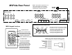
The MVP44a is the heart of a whole home music system. A MVP44a
is designed to work with 1-4 rooms or zones. Up to three MVP44a's
can be ganged together to allow up to 12 rooms or zones each
individually controlling one or two pairs of enclosure or inwall
speakers. Connection is achieved via the data port using a stereo
3.5mm jack on the rear of the MVP44a.
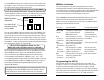
Rooms are usually controlled by a MR60 keypad. The keypads are
not intented for outdoor use. The MR60 contains an almost all
brand infrared repeater and most functions can be controlled by the
Knoll RB8 remote control. RB8 commands can easily be stored in a
learning remote. The MR60 is available with three different source
layouts (all of the MR60 keypads in one system have to have the
same source layout) and three bezel colors white, almond and ivory
for a total of 9 models. The source layout and bezel colors are easy to
change in the field.
Some rooms will not require a MR60 keypad and most MVP44a
functions can be utilized with an RB8 remote and an infrared
repeater (a MR173 IR converter is required). Up to three IR
receivers in three different rooms can be connected to a single
MR173. The MVP44a includes an internal four single or dual emitter
connection block, so emitters will have to be ordered if required. The
infrared pass through is always available when the amplifier is turned
on and in standby or powered up.
Follow directions from the speaker manufacturers when deciding
speaker locations.
Note: The MVP44a prefers 6-8 ohm speaker loads. Connecting to
4 ohm loads won't hurt the MVP44a but those channels connected
to 4 ohm loads may occasionally shut down due to overloading.
Never connect the MVP44a to 2 ohm loads.
The MVP44a has a cooling fan to increase long term power output
and reliability.
...continued
14
3
possible in the sequence to give the components settling time. For
example, sequence a power-on command: CD on, tuner on, and CD
play rather than CD on, CD play, and tuner ON.
7. Make sure the PROGRAM lamp is on.
8. Make sure the bank 1 switch is on and bank 2, 3 and 4 are off.
9. Push the SEQ (sequence) button.
10. Carefully touch (for one sec.) the wire to the bank 1 + terminal
1 to 6 where the first sequence is to be stored.
11. Move the bank 1 switch off and the bank 2 switch on.
12. Touch the wire to the terminal where the first IR signal of the
sequence is stored (for one second). Touch the wire to the
terminal where the second IR signal of the sequence is stored
(for one second). Touch any other terminals until the entire
command sequence is stored.
13. Push the SEQ button and then the PGM button to leave the
program mode (lamp goes out).
14. Move the bank 1 switch to on and bank 2, 3, and 4 to off.
The sequence is now complete.
15. Repeat steps 7 to 14 for each of the other sequences.
Note: 590-00 programming should be fully tested. Occasionally one
source component gets out of sequence especially if IR remote
controls are used (most often when using the remote to turn on and
off source components). The system user should be shown how to
correct for a source component getting out of sequence.
Caution: The MVP44a contains no user serviceable parts, so
do not attempt to open or repair the MVP44a. Refer servicing to
a qualified technician only or contact the factory for information.