
Car Amplifier User Manual


12
5
Installation
It is very important to use a top quality RJ45 8/8 crimper
tool. We strongly suggest using a cat 5 / RJ45 electronic
tester to verify the wire conductors.
Installing the MVP44a should be relatively easy. With a bit of
planning, the MVP44a will give trouble free service for years.
1. The most important consideration when installing the
MVP44a is cooling. The MVP44a has a lot of power packed into a
small chassis size. When installing it in an equipment stack, it should
be the top component. It needs at least 1-3/4" of space above the
MVP44a to allow for adequate cooling.
2. When installing the MVP44a in a rack we suggest adding a
1-3/4" blank above and below the MVP44a. In multiple MVP44a
installations, plan for a 3-1/2" blank (double) between each MVP44a
and a 1-3/4" blank on the top and bottom. Amplifiers should
always be the top components in a rack system.
3. If MVP44a channels frequently shut down due to overheating,
either the output levels will have to go down or 8 ohm speakers
installed. If 8 ohm speakers are installed on all channels and some
channels still shut down, call the factory for advice.
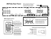
4. Connect the MVP44a inputs to the source component outputs with
good quality, short as possible RCA jack cables. Connect each
channel individually.
5. If source D is not being used we suggest you short both of them
out with a RCA shorting jack. This will make the room speakers
quieter in standby modes.
6. Connect the MVP44a speaker outputs to speakers using good
quality speaker wire. Minimum 16 gauge copper wire is
recommended with 14 gauge minimum for runs over 30' (10m)
Make sure the speakers in each room are connected in phase.
gather all the source remotes (with batteries inserted) near the 590-
00. Screw one end of a temporary wire to the 590-00 terminal
marked +12VDC. Power up the 590-00 and the MVP44a.
The 590-00 can learn up to 16 different commands on each of its
four banks. If more than 10 different IR commands are being stored
use bank 2, 3, and 4 to store the sequence commands and bank one
positions 1-6 to execute the sequences.
Single IR Command Storing
Start by pushing the RES (reset) button on the back of the
590-00. If any of the six relay activations have a single command
(not a sequence of commands), program the single command(s) first.
For example if the jazz station tuner is on source C and you want to
program the IR command "scan" (two or more news stations have
been programmed in the news station tuner) into function C, program
the 590-00 with this first.
1. Make sure the bank 1 dip switch is on; bank 2, 3, and 4 off.
2. Push PGM (program lamp goes on).
3. Using the wire attached to the 590-00 +12VDC, touch and
hold the other end of the wire to the 590-00 upper + row
terminal 2. While holding the wire in place, push the tuner
remote control button "scan" while it is about 2-4 inches from
the 590-00 internal infrared sensor. The 590-00 PROGRAM
lamp will flicker while storing the IR signal. When the IR signal
is stored, the confirm lamp comes on. Release the remote
control button and release the wire to the upper row terminal.
The IR signal is now stored in the 590-00 bank 1 terminal 2.
4. Store any other single commands in bank 1 positions 1 and 3-6.
5. Push PGM (program lamp will go out).
590-00 Sequence IR Command Storing
The six MVP44a pulse activations can activate a sequence of up to 10
IR commands each. As an overview, the individual IR commands
are first learned and stored in any of the 16 positions in the four
banks (except bank 1 positions 1 through 6), then assembled in order
Note: Ideally the MVP44a likes 6-8 ohm loads. Connecting to
4 ohm loads won't hurt the MVP44a but those channels
connected to 4 ohm loads may occasionally shut down due to
overloading. Never connect the MVP44a to 2 ohm loads.