
Car Amplifier User Manual


6
11
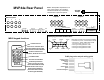
7. Install MR60 keypads (or infrared receivers) in the rooms with
the speakers. Cat 3 or cat 5 wire can be home run to the MVP44a or
up to three rooms daisy chained on one wire.
***Be sure to set the dip switch on the rear of the MR60***
See the dip switch adjustment below. Connect all eight individual
wires using RJ45 connectors. Four wire conductors are needed for
each keypad (one unique, common: IR , ground and 12VDC).
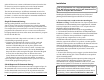
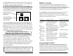
MR60 Dip Switch
Adjustment
Use either RJ45
connector as they
are in parallel
The rear of the MR60 is shown. Because one to three MR60's can
be connected or daisy chained to the same cat 5 wire, the keypad
position on the wire must be selected using the dip switch. The two
MR60 RJ45 connectors are in parallel. Only one dip switch slider
should be on and the other two off (#1 is shown on in this example).
The MR60 1-2-3 dip switch positions correspond to MVP44a keypad
ports and speaker outputs A3 or B1-B2-B3.
***Even if the keypads are home run, the
MR60 dip switch position has to be selected***
If three keypads are daisy chained on one wire, select the MR60
dip switch on the first MR60 to one, the second MR60 to two and
the third MR60 to three. At the rear of the MVP44a, the RJ45
connector from the three MR60 keypads can be connected any
corresponding keypad Bank A3 or Bank B; port 1, 2 or 3. The
corresponding speaker outputs will be the same number as selected
on the MR60 keypad (example: the MR60 keypad with #2 dip on
and connected to MVP44a keypad bank B will control speaker
outputs B2R and B2L).
After installation, if the keypads are not working properly or not
controlling at all, Check the MR60 dip switch settings, wiring
layout and crimp as well as bank connections very carefully.
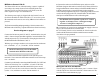
MR60
1 2 3 4
MVP44a Activation
The 590-00 generates infrared command sequences when a
momentary pulse from any of the six MVP44a function outputs are
activated. Source A is usually reserved for CD use. When the MVP44a
is powered up someone pushing a MR60 Source button or RB8
remote source, the power on (TON) pulse is activated.
Some examples to understand when MVP44a pulses are activated
and the 590-00 macro sequencies are initiated are listed below:
Note: None of the functions below work when any MR60 leds are
blinking to indicate MUTE activated.
Pulse O/P Activates when: Example IR sequence:
Power On Any MR60 or RB8 source Sequence power (on)
(TON) key is pushed when all command to all
MR60 leds are off. source components
F A FNC then Source A (CD) CD skip, CD play or
(source A key pushed when system's on CD random
CD player) and no MR60 blinking led's.
F B FNC then Source B (FM or CD skip to next disk
(source B AUX1) key pushed when
Jazz station) the system is on.
F C FNC then Source C (Dish Scan to next news
(source C AM or CD2) key pushed station programmed
news tuner) when the system is on. into news tuner
F D FNC then Source D (AUX or Scan up one station
(source D AUX2) key pushed when
sat dish#2) the system is on.
Programming the 590-00
IR functions do not have to be related to the source input. For
example, if source A is a CD player and source B is a jazz tuner,
function A could be a sequence of CD skip, CD play, and CD
random. Function B could be CD Skip to next disk. After deciding
and writing down the commands to be programmed for each of the
six pulse activations (Function A, B, C, D, TON and TOFF),