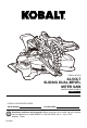
ITEM # 1051232 24-VOLT SLIDING DUAL-BEVEL MITER SAW MODEL # KMS 0724B-03 Español p. 35 ATTACH YOUR RECEIPT HERE Serial Number Purchase Date Questions, problems, missing parts? Before returning to your retailer, call our customer service department at 1-888-3KOBALT (1-888-356-2258), 8 a.m. - 8 p.m., EST, Monday - Friday.
TABLE OFCONTENTS Product Specifications....................................................................................... 2 Package Contents…......................................................................................... 3 Safety Information…......................................................................................... 4 Preparation...................................................................................................... 10 Tools Needed..................................
PACKAGECONTENTS Unpacking • Carefully lift the miter saw from the carton and place it on a level worksurface. NOTICE: This tool is heavy. To avoid back injury, lift with your legs, not your back, and get help when needed. • Use the main handler to lift the saw arm; do not lift the saw by the saw arm. • This saw has been shipped with the saw arm secured in the “DOWN” position. To release the saw arm, push down on the top of the saw arm, and pull out the arm-lockpin.
SAFETY INFORMATION Please read and understand this entire manual before attempting to assemble or operate this product. If you have any questions regarding the product, please call customer service at 1-888-3KOBALT, 8 a.m. - 8 p.m., EST, Monday - Friday. WARNING • The operation of any power tool can result in foreign objects being thrown into your eyes, which can result in severe eye damage.
SAFETY INFORMATION Some of the following symbols may be used on this tool. Please study them and their meaning. Proper interpretation of these symbols will allow you to operate the tool better and more safely. SYMBOL DEFINITION SYMBOL DEFINITION V Volts n0 No-load Speed Direct Current RPM Revolutions per Minute Degrees Fahrenheit °C Degrees Celsius or d.c. °F No-Hands Zone. Failure to keep your hands away from the blade will result in serious personal injury.
SAFETY INFORMATION • Do not abuse the cord. Never use the cord for carrying, pulling or unplugging the power tool. Keep cord away from heat, oil, sharp edges or moving parts. Damaged or entangled cords increase the risk of electric shock. • When operating a power tool outdoors, use an extension cord suitable for outdoor use. Use of a cord suitable for outdoor use reduces the risk of electric shock.
SAFETY INFORMATION • Keep cutting tools sharp and clean. Properly maintained cutting tools with sharp cutting edges are less likely to bind and are easier to control. • Use the power tool, accessories and tool bits etc. in accordance with these instructions, taking into account the working conditions and the work to be performed. Use of the power tool for operations different from those intended could result in a hazardous situation.
SAFETY INFORMATION • The workpiece must be stationary and clamped or held against both the fence and the table. Do not feed the workpiece into the blade or cut “freehand” in any way. Unrestrained or moving workpieces could be thrown at high speeds, causing injury. • Push the saw through the workpiece. Do not pull the saw through the workpiece. To make a cut, raise the saw head and pull it out over the workpiece without cutting, start the motor, press the saw head down and push the saw through the workpiece.
SAFETY INFORMATION • After finishing the cut, release the switch, hold the saw head down and wait for the blade to stop before removing the cut-off piece. Reaching with your hand near the coasting blade is dangerous. • Hold the handle firmly when making an incomplete cut or when releasing the switch before the saw head is completely in the down position. The braking action of the saw may cause the saw head to be suddenly pulled downward, causing a risk of injury.
PREPARATION Know Your Miter Saw This miter saw can be used for the purpose listed: cross cutting wood products and plastic; bevel cutting and compound cutting wood products and plastics . The safe use of this product requires an understanding of the information on the tool and in this operator’s manual, as well as knowledge of the project you are attempting. Before attempting to use the saw, familiarize yourself with all of its operating features and safety requirements.
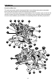
PREPARATION PART DESCRIPTION PART DESCRIPTION A Lock-off buttons P Miter-control lever B On/Off switch Q Lower blade guard C LED switch R Main handle D Upper blade guard S Spindle-lock button E Dust-extraction port T Fixed fence F Depth-control knob U Sliding fence (left and right) G Bevel-angle indicator V Fence-lock knob (left and right) H Bevel scale W Clamp receptacle (left and right) I Bevel-change lever X 45° bevel stop J Mounting holes (8) Y 33.
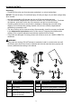
ASSEMBLY INSTRUCTIONS This product requires assembly. WARNING • If any parts are damaged or missing, do not operate this tool until the missing parts are replaced. Failure to heed this warning could result in serious personal injury. • Always make sure that the miter saw is securely mounted to a workbench or an approved work stand. Failure to heed this warning can result in serious personal injury. • Battery tools are always in operating condition.
ASSEMBLY INSTRUCTIONS 2. Carrying Handle a. Align the holes on the saw arm with the holes in the carrying handle (AD), then install the carrying handle onto the arm. b. Insert the long screw with the spring washer and flat washer (6) into the hole in the carrying handle. Tighten the long screw it with the double ended wrench (4). c. Insert the two short screws with the spring washers and flat washers (7) into the holes in the carrying handle. The two short screws with the double ended wrench.
ASSEMBLY INSTRUCTIONS 5. Locking/Unlocking the Saw Arm When locking and unlocking the saw arm, it is not necessary to loosen the depth-control knob. 5 R AC To unlock and raise the saw arm: a. Firmly grasp the main handle (R) and apply downward pressure while at the same time pulling the arm-lock pin (AC) out and away from the saw housing. b. Release the arm-lock pin and slowly raise the saw arm. To lock the saw arm: a. Firmly grasp the main handle (R) and apply downward pressure until head stops. b.
ADJUSTMENT INSTRUCTIONS The miter saw is properly set and adjusted prior to shipping. The adjustments were made at the factory and normally do not require re-adjustment. If, in the course of use, adjustments are required, please follow the directions below. WARNING • Battery tools are always in operating condition. Therefore, always remove the battery pack from the tool before making any adjustments or installing accessories, failure to do could result in accidental starting causing serious injury. 6.
ADJUSTMENT INSTRUCTIONS 7. Miter-Angle Indicator Adjustment a. Remove the battery from the tool. b. Square the blade to the fence, to make sure that the blade is 90° to the fence and the miterdetent locking system is engaged. Press the miter-control lever (P) to lock the miter angle. c. Loosen the miter-angle indicator screw and adjust the miter-angle indicator (N) to the “0” mark on the miter scale (M). d. Tighten the miter-angle indicator screw. 7 M screw N P 8. Squaring the Blade to the Table a.
ADJUSTMENT INSTRUCTIONS 9. Bevel-Angle Indicator Adjustment a. Remove the battery pack from the tool. b. Square the blade to the table to make sure that the blade is 90° to the table. c. Rotate the bevel-lock knob to lock the bevel. d. Check to see if the bevel-angle indicator (G) is pointing to 0° on the bevel scale (H). e. If the indicator is not pointing to 0°, loosen the bevel-angle indicator screw, adjust the indicator to 0° on bevel scale and then retighten the screw. 9 screw G H 10.
ADJUSTMENT INSTRUCTIONS 11. Miter-control Lever Adjustment NOTE: This adjustment was made at the factory and, under normal circumstances, it does not require re-adjustment. 11 In the lock position, the miter-control lever (P) should feel tight and secure and considerable effort should be required to move the miter table. If the mitercontrol lever feels loose or the table moves easily when in the locked position, and adjustment to the miter-control lever is required. Throat plates P To adjust Lock nut a.
OPERATING INSTRUCTIONS When transporting the saw, turn off the saw and remove the battery pack from the miter saw, then lower the saw arm and lock it in the “DOWN” position. Lock the saw arm by depressing the arm-lock pin (AC). A carrying handle (AD) is located on the top of the saw arm. Never lift the saw by the main handle on the front end of the saw arm or by the fence. Always maintain a speed and pressure that will allow cutting without overheating the saw blade.
OPERATING INSTRUCTIONS 14. Blade Change 14 To Remove the Blade O blade outer bolt flang bladebolt guard WARNING screw • Use protective gloves when removing or installing the blade. Do not touch the blade teeth to avoid 4 S injury. a. Remove the battery pack from the saw. b. Raise the saw arm. c. Lift and hold the lower blade guard (Q); loosen the screw fixed on the blade-bolt screw guard with the double ended wrench (4). d. Rotate the blade-bolt guard to expose the blade bolt. e.
OPERATING INSTRUCTIONS 15. Sliding Fence 15 CAUTION • Adjust and fasten the fences properly before cutting. V The sliding fences (U) are adjustable to accommodate different sized work pieces. Loosen the fence-lock knobs (V) on the sliding fences away from the blade to make sure that the blade can not contact the fence. When making a crosscut or a miter cut, move the sliding fences closer to the blade to better support the work piece.
OPERATING INSTRUCTIONS 18. ON/OFF Switch For safety, the On/Off switch (B) is designed to prevent accidental starts. 18 hole B A a. To operate the saw, press the lock-off button (A) to disengage the lock, then squeeze the On/Off switch. WARNING • The blade should reach full speed before it contacts the work piece. b. To turn off the saw, release the On/Off switch, and allow the blade to come to a complete stop. WARNING! • Make the On/Off trigger switch childproof.
OPERATING INSTRUCTION 20. Slide Cuts This type of cut is used mainly for wide pieces. Loosen the sliding-lock knob (AB), then pull the saw arm towards the operator. Lower the saw arm into the work piece and then push it to the rear of the saw to make the cut. 20 WARNING • Never pull the saw toward you during a cut. The blade can suddenly climb up on top of the work piece and force itself toward you. • Follow these instructions for making your slide cut: a. Remove the battery pack from the saw. b.
OPERATING INSTRUCTIONS g. Attach the battery pack to the saw. h. Pull out the arm-lock pin to release the saw arm. i. Place the work piece flat on the miter table with one edge securely against the fence. If the board is warped, place the convex side against the fence. If the concave edge of the board is against the fence, the board could collapse on the table at the end of the cut and jam the blade (see Cutting Warped Material). j.
OPERATING INSTRUCTIONS 22. Bevel Cutting A bevel cut is a cut made across the grain of the work piece with the blade at an angle other than 90° to the miter table and the work piece. A straight bevel cut is made with the miter table set at the 0° position and with the saw head set at a bevel angle between 0° and 48° left, or 0° and 46° right. 22 R 2 a. Remove the battery pack from the saw. b. Mark the cutting line on the work piece with a pencil. c.
OPERATING INSTRUCTIONS l. Before turning the saw on, perform a trial of the cutting operation by lowering the saw arm to make sure that no problems will occur when the cut is made. m. Hold the main handle (R), and use the On/Off switch (B) to turn the saw on. Allow several seconds for the blade to reach maximum speed before cutting. n. Slowly lower the blade into and through the work piece. o. Release the On/Off switch. Allow the saw blade to stop rotating before raising the blade out of the work piece.
OPERATING INSTRUCTIONS NOTE: To obtain correct bevel angles, rotate the bevel-stop lever (I) to the other side to pull it out, and tilt the saw to the desired angle. h. When the saw arm has been set at the desired angle, rotate the bevel-lock knob to securely tighten it. i. Connect the saw with the battery pack. j. Place the work piece flat on the miter table, with one edge securely against the fence. If the board is warped, place the convex side against the fence.
OPERATING INSTRUCTIONS 24. Grooves The cutting depth adjustment is a feature used when cutting grooves in the work piece. The depth control knob (F) is used to limit the blade depth. A groove should be cut as a slide cut. 24a F Always make a practice cut on scrap wood before cutting the work piece. a. Remove the battery pack from the saw. b. With the depth-control knob (F) touching the depth stop, rotate the depth control knob to the desired cutting depth. c.
OPERATING INSTRUCTIONS 25. Cutting Warped Material 25a WARNING • To avoid kickback and serious personal injury, never position the concave side of bowed or warped material against the fence. When cutting warped material, be certain that the material to be cut is positioned on the miter table with the convex side against the fence, as show. If the warped material is positioned the wrong way, it will pinch the blade near the end of the cut. 26.
OPERATING INSTRUCTIONS 27. Cutting Crown Molding 27 WARNING • Always use the work piece clamp, and place tape on the area being clamped to avoid marks on the work piece. Your miter saw is ideal for cutting crown molding. To fit properly, crown molding must be compoundmitered with extreme accuracy. Since compound cuts are the most difficult to accurately obtain, trial cuts should be made in scrap material, and much thought and planning invested prior to making your required cut.
OPERATING INSTRUCTIONS 29. Cutting Crown Molding against the Miter Fence To nest pieces of crown molding less than 3-5/8 in. tall: 29 52° celling 38° wall a. Remove the battery pack from the saw. b. Set the bevel angle at 0° and the miter angle at fence 45°, to either the left or the right as needed. 38° c. Lay the crown molding on the saw with its 52° bottom edge resting at a natural angle flush against the fence and its top edge resting flush against the miter table. d.
CARE AND MAINTENANCE All maintenance should only be carried out by a qualified service technician. Cleaning WARNING • Before cleaning or performing any maintenance, remove the battery pack from the miter saw. For safe and proper operation, always keep the tool and its ventilation slots clean. • Always wear safety goggles or safety glasses with side shields when blowing dust. If operation is dusty, also wear a dust mask.
TROUBLESHOOTING WARNING • Turn the switch to the “OFF” position, and remove the battery pack from the miter saw before performing troubleshooting procedures. PROBLEM The tool does not work. Blade binds, jams, or burns the wood. POSSIBLE CAUSE CORRECTIVE ACTION Battery capacity is low. Charge the battery. 1. Improper operation. 2. Dull blade. 1. See “OPERATING INSTRUCTIONS” section. 3. Improper blade. 2. Replace or sharpen blade. 3. Replace blade. Saw vibrates or shakes. 1. Damaged blade. 2.
ARTÍCULO # 1051232 24-VOLT SIERRA INGLETADORADESLIZANTE DE DOBLE BISEL MODELO # KMS 0724B-03 ADJUNTE SU RECIBO AQUÍ Número de serie Fecha de compra ¿Preguntas, problemas, piezas faltantes? Antes de volver a la tienda, llame a nuestro Departamento de Servicio al Cliente al: 1-888-3KOBALT (1-888-356-2258), 8 a.m. a 8 p.m., hora estándar del Este.
ÍNDICE Especificaciones del producto......................................................................... 36 Contenido del paquete…................................................................................ 37 Información de seguridad…............................................................................ 38 Preparación..................................................................................................... 45 Herramientas necesarias.................................................
CONTENIDO DEL PAQUETE Desembalaje • Extraiga la sierra ingletadora de la caja cuidadosamente y colóquela sobre una superficie de trabajo nivelada. AVISO: Esta herramienta es pesada. Para prevenir lesiones en la columna, levante con sus piernas, no con la espalda, y solicite ayuda cuando sea necesario. • Use la manija principal para levantar el brazo de la sierra, no levante la sierra por el brazo de la sierra. • Esta sierra se envió con el brazo de la sierra asegurado en la posición “DOWN” (ABAJO).
INFORMACIÓN DE SEGURIDAD Lea y comprenda completamente este manual antes de intentar ensamblar, usar o instalar el producto. Si tiene preguntas relacionadas con el producto, llame a nuestro Departamento de Servicio al Cliente al 1-800-643-0067, de lunes a jueves de 8 a.m. a 6 p.m., y los viernes de 8 a.m. a 5 p.m., hora estándar del Este. ADVERTENCIA • Durante el funcionamiento de cualquier herramienta eléctrica, pueden entrar objetos extraños a los ojos y causar graves daños oculares.
INFORMACIÓN DE SEGURIDAD Algunos de los siguientes símbolos pueden aparecer en esta herramienta. La interpretación correcta de estos símbolos le permitirá utilizar la herramienta de manera eficaz y segura. SÍMBOLO DEFINICIÓN SÍMBOLO DEFINICIÓN V Voltios n0 Velocidad sin carga Corriente continua RPM Revoluciones por minuto Grados Fahrenheit °C Grados Celsius o CC. °F Área de riesgo de las manos. Si no mantiene sus manos alejadas de la hoja, sufrirá lesiones corporales graves.
INFORMACIÓN DE SEGURIDAD • Evite el contacto del cuerpo con superficies conectadas a tierra, como tuberías, radiadores, extractores o refrigeradores. Existe un riesgo adicional de descarga eléctrica si su cuerpo está en contacto con una puesta a tierra. • No exponga las herramientas eléctricas a la lluvia o a condiciones de humedad. Si ingresa agua en una herramienta eléctrica, el riesgo de descarga eléctrica aumentará. • No maltrate el cable.
INFORMACIÓN DE SEGURIDAD • No utilice la herramienta eléctrica si el interruptor no la enciende o apaga. Cualquier herramienta eléctrica que no pueda controlarse con el interruptor es peligrosa y debe repararse. • Desconecte el enchufe de la fuente de alimentación o retire el paquete de baterías de la herramienta eléctrica (si es posible) antes de realizar cualquier ajuste, cambiar accesorios o almacenarla.
INFORMACIÓN DE SEGURIDAD • No exponga el paquete de baterías ni la herramienta al fuego o a una temperatura excesiva. La exposición al fuego o a las temperaturas por encima de los 130 °C puede causar una explosión. • Siga todas las instrucciones de carga y no cargue el paquete de baterías ni las herramientas fuera del rango de temperatura especificado en las instrucciones. La carga inadecuada o a temperaturas fuera del rango especificado podría dañar la batería y aumentar el riesgo de incendio.
INFORMACIÓN DE SEGURIDAD No debe haber clavos u objetos extraños en la pieza de trabajo. • No utilice la sierra hasta que en la mesa no haya ninguna herramienta, resto de madera, etc., salvo la pieza de trabajo. Los desechos pequeños, las piezas de madera sueltas u otros objetos que entren en contacto con la cuchilla mientas gira pueden ser expulsados a alta velocidad. • Corte solo una pieza de trabajo a la vez.
INFORMACIÓN DE SEGURIDAD Advertencias adicionales de seguridad para la sierra ingletadora ADVERTENCIA • El uso de esta herramienta puede generar o dispersar polvo, lo que podría causar daños respiratorios permanentes y graves, además de otras lesiones. Siempre use la protección adecuada para la exposición al polvo. Dirija las partículas lejos del rostro y el cuerpo. • Conozca su herramienta eléctrica. Lea atentamente el manual del operador.
PREPARACIÓN Conozca la sierra ingletadora Esta sierra ingletadora se puede usar para el propósito indicado a continuación: para cortes transversales de productos de madera y materiales de plástico; para cortes de bisel y compuestos en productos de madera y plástico. El uso seguro de este producto requiere de la comprensión de la información en la herramienta y en el manual del operador, además del conocimiento sobre el proyecto que intenta llevar a cabo.
PREPARACIÓN PIEZA DESCRIPCIÓN PIEZA DESCRIPCIÓN A Botones de bloqueo P Palanca de control de inglete B Interruptor de encendido/apagado Q Protección inferior de la hoja C Interruptor de la luz LED R Manija principal D Protección superior de la hoja S Botón de bloqueo del husillo E Puerto de extracción de polvo T Guía fija F Perilla de control de profundidad U Guía corrediza (izquierda y derecha) G Indicador del ángulo de bisel V Perilla de bloqueo de la guía (izquierda y derech
PREPARACIÓN HERRAMIENTAS NECESARIAS Las siguientes herramientas (no se incluyen) se necesitan para realizar los ajustes o la instalación.
INSTRUCCIONES DE ENSAMBLAJE Este producto requiere de ensamblado. ADVERTENCIA • Si hay piezas dañadas o faltantes, no utilice esta herramienta hasta reemplazar dichas piezas. No seguir esta advertencia podría provocar graves lesiones personales. • Siempre asegúrese de que la sierra ingletadora esté instalada de forma segura a un banco de trabajo o a un puesto de trabajo aprobado. No seguir esta advertencia puede provocar graves lesiones personales.
INSTRUCCIONES DE ENSAMBLAJE 2. Manija de transporte a. Alinee los orificios en el brazo de la sierra con los orificios en la manija de transporte (AD), luego instale la manija de transporte en el brazo. b. Inserte el tornillo largo con la arandela de resorte y la arandela plana (6) dentro del orificio en la manija de transporte. Apriete el tornillo largo con la llave doble (4). c.
INSTRUCCIONES DE ENSAMBLAJE 5. Bloqueo/desbloqueo del brazo de la sierra Cuando bloquee y desbloquee el brazo de la sierra, no es necesario aflojar la perilla de control de seguridad. 5 R AC Para desbloquear y levantar el brazo de la sierra, haga lo siguiente: a. Sujete firmemente la manija principal (R) y aplique presión hacia abajo, al mismo tiempo que jala el pasador de bloqueo del brazo (AC) hacia afuera de la carcasa de la sierra. b.
INSTRUCCIONES DE ENSAMBLAJE La sierra ingletadora se ajusta y regula correctamente antes del envío. Los ajustes vienen de fábrica y, por lo general, no requieren correcciones. Si, durante el uso, se requieren ajustes, siga las instrucciones a continuación. ADVERTENCIA • Las herramientas a batería siempre están en condiciones de funcionamiento.
INSTRUCCIONES DE AJUSTE 7. Ajuste del indicador del ángulo de inglete a. Retire la batería de la herramienta. b. Ponga a escuadra la hoja con la guía para asegurarse de que la hoja está a 90° de la guía y que el sistema de bloqueo del freno de inglete está enganchado. Presione la palanca de control de inglete (P) para bloquear el ángulo de inglete. c. Afloje el tornillo del indicador del ángulo de inglete y regule el indicador del ángulo de inglete (N) en la marca “0” en la escuadra de inglete (M). d.
INSTRUCCIONES DE AJUSTE 9. Ajuste del indicador del ángulo de bisel a. Retire el paquete de baterías de la herramienta. b. Ponga a escuadra la hoja con la mesa para asegurarse de que la hoja está a 90° de la mesa. c. Gire la perilla de bloqueo de bisel para bloquear el bisel. d. Verifique si el indicador del ángulo de bisel (G) apunta a 0° en la escala de bisel (H). e.
INSTRUCCIONES DE AJUSTE 11. Adjuste de la palanca de control de inglete NOTA:este ajuste viene de fábrica y, por lo general, no requiere correcciones. 11 En la posición de bloqueo, la palanca de control de inglete (P) debe sentirse apretadas y fijas, y se debe requerir un esfuerzo considerable para mover la mesa de inglete. Si la palanca de control de inglete está floja o la mesa se mueve fácilmente cuando se encuentra en la posición de bloqueo, se requiere un ajuste de la palanca de control de inglete.
INSTRUCCIONES DE AJUSTE ADVERTENCIA • Para evitar el riesgo de lesiones personales, si el movimiento se siente apretado o si hay juego en el pivote de bisel, permita que un técnico de servicio calificado repare la sierra antes de usarla. Cuando transporte la sierra, apáguela y retire el paquete de baterías de la sierra ingletadora, luego baje el brazo de la sierra y bloquéelo en la posición “DOWN” (ABAJO). Bloquee el brazo de la sierra al presionar el pasador de bloqueo del brazo (AC).
INSTRUCCIONES DE FUNCIONAMIENTO ADVERTENCIA • Las herramientas a batería siempre están en condiciones de funcionamiento. Por lo tanto, siempre retire el paquete de baterías de la herramienta cuando la herramienta no se encuentre en uso o cuando la transporta. 14. Cambio de hoja Para retirar la hoja 14 reborde O protector ADVERTENCIA exterior del perno perno de • Use guantes de protección cuando retire o instale de la hoja la hoja la hoja. Para evitar lesiones, no toque los dientes de la hoja. tornillo a.
INSTRUCCIONES DE FUNCIONAMIENTO Sistema del protector de hoja El protector de hoja inferior (Q) en la sierra está diseñado para brindar protección y seguridad al operador. No lo modifique por ningún motivo. ADVERTENCIA • Para evitar posibles lesiones graves, nunca use la sierra cuando la protección de hoja inferior no funcione correctamente.
INSTRUCCIONES DE FUNCIONAMIENTO 17. Luz de trabajo LED El sistema de iluminación LED proyecta una sombra de la hoja en la pieza de trabajo. Esto genera una mayor precisión de corte y no requiere ajustes. 17 C sombra de la hoja Para encender la luz LED, presione el interruptor de la luz LED (C).
INSTRUCCIONES DE FUNCIONAMIENTO f. Fije la batería a la sierra. g. Antes de encender la sierra, baje el brazo de la sierra para asegurarse de que la abrazadera libere la protección baja y el brazo de la sierra. 19 ADVERTENCIA • Utilice una posición de sujeción que no interfiera con la operación de corte. 2 h. Encienda la sierra. Siempre permita que la hoja alcance la velocidad máxima antes de empezar a cortar. Baje el brazo de la sierra y realice el corte. i.
INSTRUCCIONES DE FUNCIONAMIENTO j. Libere el interruptor de encendido/apagado. Espere hasta que la hoja se detenga por completo antes de regresar el brazo de la sierra a la posición elevada. Luego, retire la pieza de trabajo. 21. Corte transversal Un corte transversal es un corte que se realiza a través del grano de la pieza de trabajo. Un corte transversal recto es un corte que se realiza con la mesa de inglete ajustada en la posición de 0°.
INSTRUCCIONES DE FUNCIONAMIENTO ADVERTENCIA • Para evitar lesiones personales graves, siempre apriete firmemente la palanca de control de inglete antes de realizar un corte. No hacerlo podría provocar el movimiento del brazo de control o de la mesa de inglete mientras realiza un corte. • Nunca utilice a otra persona como un soporte adicional para una pieza de trabajo que es más larga o más ancha que la mesa de la sierra básica, o para empujar, sostener o jalar la pieza de trabajo.
INSTRUCCIONES DE FUNCIONAMIENTO NOTA: utilice el tope de bisel (W, Y) para ubicar rápidamente los ángulos de bisel de 33,9° y 45°. f. Gire la perilla de bloqueo de bisel para apretarlos bien. ADVERTENCIA • Afloje la guía corrediza y coloque la guía de modo que no interfiera con el ensamble de la sierra durante el corte y, luego, vuelva a apretar la guía. g. Fije el paquete de baterías a la sierra. h.
INSTRUCCIONES DE FUNCIONAMIENTO 23. Corte de inglete compuesto ADVERTENCIA • Cuando realice un corte con un ángulo de bisel, deslice la guía corrediza superior (U) lejos de la línea de corte. 23 Un corte de inglete compuesto es un corte que se realiza con un ángulo de inglete y un ángulo de bisel al mismo tiempo. Este tipo de corte se utiliza para molduras decorativas, marcos de cuadros y otras uniones finas.
INSTRUCCIONES DE FUNCIONAMIENTO k. Encienda el interruptor de luz LED (C) y alinee la línea de lápiz con la línea de sombra de la hoja. l. Utilice la abrazadera de fijación (2) para asegurar la pieza de trabajo contra la guía y la mesa de la sierra. m. Cuando corte un pieza de trabajo larga, utilice un bloque (no incluido) para sostener la pieza.
INSTRUCCIONES DE FUNCIONAMIENTO b. Con la perilla de control de profundidad (F) tocando el tope de profundidad, gírela hasta la profundidad de corte deseada. c. Aleje la pieza de trabajo de la guía con un espaciador de madera con un grosor aproximado de 3,81 cm. Esto permitirá que se corte una ranura completa. Asegúrese de que la pieza de trabajo esté completamente apoyada. d. Fije el paquete de baterías a la sierra. e. Corte los dos bordes exteriores de la ranura. f.
INSTRUCCIONES DE FUNCIONAMIENTO NOTA: siempre realice un corte de “funcionamiento en seco” para que pueda determinar si la operación que se intenta realizar es posible antes de que se suministre energía a la sierra ingletadora. c. Utilice el interruptor de LED (C) para encender la luz LED y alinee la línea de lápiz con la línea de sombra de la luz LED. d. Cuando corte piezas de trabajo largas, utilice un soporte adicional. e.
INSTRUCCIONES DE FUNCIONAMIENTO Ajuste de inglete Ajuste de bisel IL Derecha 31,6° Izquierda 33,9° IR Izquierda 31,6° Derecha 33,9° OL Izquierda 31,6° Derecha 33,9° OR Derecha 31,6° Izquierda 33,9° Llave Tipo de corte Esquina interior izquierda 1. Coloque la parte superior de la moldura contra la guía. 2. El lado IZQUIERDO es la pieza acabada Esquina interior derecha 1. Coloque la parte superior de la moldura contra la guía. 2.
INSTRUCCIONES DE FUNCIONAMIENTO NOTA: la ventaja de cortar molduras tipo corona con este método es que no se requiere un corte biselado. Se pueden realizar cambios mínimos en el ángulo de inglete sin afectar el ángulo de bisel. De esta manera, cuando se encuentran esquinas que no sean de 90°, la sierra se puede regular de forma rápida y sencilla para estas. Para conocer los ajustes de inglete correctos, vea la tabla a continuación.
CUIDADO Y MANTENIMIENTO Todas las tareas de mantenimiento deben estar a cargo únicamente de un técnico de servicio calificado. Limpieza ADVERTENCIA • Antes de limpiar o realizar cualquier mantenimiento, retire el paquete de baterías de la sierra ingletadora. Para un uso seguro y adecuado, siempre mantenga limpias la herramienta y sus ranuras de ventilación. • Use siempre gafas o lentes seguridad con protecciones laterales cuando sople el polvo.
SOLUCIÓN DE PROBLEMAS ADVERTENCIA • Coloque el interruptor en la posición “OFF” (APAGADO) y retire el paquete de baterías de la sierra ingletadora antes de realizar procedimientos de solución de problemas. PROBLEMA La herramienta no funciona. CAUSA POSIBLE La capacidad de la batería es baja. 1. Funcionamiento inadecuado. La hoja se dobla, atasca o quema la madera. La sierra vibra o se agita. 2. Hoja roma. 3. No está usando la hoja adecuada. 1. Hoja dañada. 2. Hoja suelta.