
Use and Care Guide


17
ADJUSTMENT INSTRUCTIONS
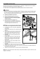
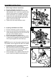
9. Bevel-Angle Indicator Adjustment
a. Remove the battery pack from the tool.
b. Square the blade to the table to make sure that
the blade is 90° to the table.
c. Rotate the bevel-lock knob to lock the bevel.
d. Check to see if the bevel-angle indicator (G) is
pointing to 0° on the bevel scale (H).
e. If the indicator is not pointing to 0°, loosen the
bevel-angle indicator screw, adjust the indicator
to 0° on bevel scale and then retighten the
screw.
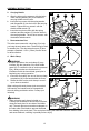
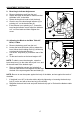
10. Adjusting the Blade to the Miter Table 45°
Bevel, 0° Miter
a. Remove the battery pack from the tool.
b. Loosen the bevel-lock knob (AA) to release the
bevel. Move the left sliding fence (U) all the way
out along the horizontal direction.
c. Pull the 45° stop block (X) toward the rear of the
saw.
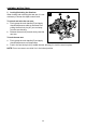
d. Tilt the saw head to set the bevel-angle to 45°.
NOTE: To obtain correct bevel angles, rotate the
bevel-stop lever (I) to the other side to pull it out, and
tilt the saw head to the desired angle.
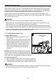
e. Place a combination square (not included) on
the miter table with the rule against the table and
the heel of the square against the saw blade (O).
NOTE: Be sure to rest the square against the body of the blade, and not against the teeth of
the blade.
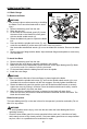
f. If the blade is not 45° to the miter table, adjust by tightening or loosening the bevel-stop
bolt (Z) on the tool with a 6mm hex key (not included).
g. Retighten the bevel-lock knob and push the bevel-stop pin in. Recheck the blade-to-table
alignment.
9
G
H
screw
10
I
Z X Y