ITEM #1157558/0856455/0726981/0856457 BRUSHLESS BLOWER MODEL #KHB 4124B-03 Español p. 13 WARNING Read all safety warnings and instructions. Failure to follow the warnings and instructions may result in electric shock, fire and/or serious injury. ATTACH YOUR RECEIPT HERE Serial Number Purchase Date Questions, problems, missing parts? Before returning to your retailer, call our customer service department at 1-888-3KOBALT (1-888-356-2258), 8 a.m. - 8 p.m., EST, Monday - Friday.
TABLE OF CONTENTS Product Specifications....................................................................................... 2 Package Contents............................................................................................. 3 Safety Information............................................................................................. 4 Preparation........................................................................................................ 7 Assembly Instructions.................
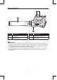
PACKAGE CONTENTS B C A D PART DESCRIPTION PART DESCRIPTION A Blower tube C Variable-speed trigger switch B Trigger-lock lever D Hanging hole WARNING • Remove the tool from the package and examine it carefully. Inspect the tool carefully to make sure that no breakage or damage occurred during shipping. If any parts are damaged or missing, please return the product to the place of purchase. Do not discard the carton or any packaging material until all parts have been examined.
SAFETY INFORMATION Please read and understand this entire manual before attempting to assemble or operate this product. If you have any questions regarding the product, please call customer service at 1-888-3KOBALT, 8 a.m. - 8 p.m., EST, Monday - Friday. WARNING • The operation of any power tool can result in foreign objects being thrown into your eyes, which can result in severe eye damage.
SAFETY INFORMATION Some of the following symbols may be used on this tool. Please study them and their meaning. Proper interpretation of these symbols will allow you to operate the tool better and more safely. SYMBOL DEFINITION SYMBOL DEFINITION V Volts n No-load Speed A Amps CFM 0 Cubic Feet per Minute WARNING- To reduce the risk of injury, user must read instruction manual.
SAFETY INFORMATION • Use only with battery packs and chargers listed below. BATTERY PACK CHARGER KB 124-03; KB 224-03; KB 424-03; KB 524-03; KB 624-03; KB 924-03 KRC 2445-03 KRC 2490-03 • Do not use a battery pack or appliance that is damaged or modified. Damaged or modified batteries may exhibit unpredictable behavior resulting in fire explosion or risk of injury. • Do not expose a battery pack or appliance to fire or excessive temperature.
SAFETY INFORMATION • Do not operate the equipment while barefoot or when wearing sandals or similar lightweight footwear. Wear protective footwear that will protect your feet and improve your footing on slippery surfaces. • Check the work area before each use. Remove all objects such as rocks, broken glass, nails, wire, or string which can be thrown by or become entangled in the machine. • Do not point the blower tube in the direction of people or pets.
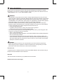
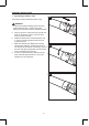
ASSEMBLY INSTRUCTIONS 1. Assembling the Blower Tube 1a This product requires assembly before using. WARNING • To prevent accidental starting that could cause serious personal injury, always remove the battery pack from the tool when assembling parts. a. Align the groove in the blower tube (A) with the knob on the blower housing. Push the tube onto the blower housing. b. Rotate the blower tube counterclockwise until a “click” is heard to signal that the knob has locked into place. c.
ASSEMBLY INSTRUCTIONS 2. To Install/Remove Battery Pack 2 To Attach Battery Pack a. Make sure that the variable-speed trigger switch (C) is in OFF position and the triggerlock lever (B) is in the OFF position. b. Align the raised portion on the battery pack (not included) with the grooves on the bottom of the tool, then slide the battery pack onto the tool as shown. c.
OPERATING INSTRUCTIONS 1. To Start/Stop the Blower The variable-speed trigger switch (C) can turn the blower ON/OFF and deliver variable speed. The blower is also equipped with a trigger-lock lever (B) to turn the blower ON/OFF, and lock the blower at a certain speed. 3 C B To Turn the Blower ON a. To turn the blower ON, depress the variablespeed trigger switch (C). b. The variable-speed trigger switch delivers higher speed with increased trigger pressure and lower speed with decreased trigger pressure.
OPERATING INSTRUCTIONS 3. Operating the Blower WARNING • Always wear eye protection with side shields marked to comply with ANSI Z87.1, along with hearing protection. Failure to do so could result in objects being thrown into your eyes and other possible serious injuries. • Do not use any attachments or accessories not recommended by the manufacturer of this product. The use of attachments or accessories not recommended can result in serious personal injury.
TROUBLESHOOTING WARNING • Turn the switch to the “OFF” position, and remove battery from the tool before performing troubleshooting procedures. PROBLEM POSSIBLE CAUSE CORRECTIVE ACTION Tool does not work. 1. Low battery capacity. 1. Charge the battery pack. 2. The battery pack or blower is too hot. 2. Turn off the blower and allow the blower and battery pack to cool. The air inlet is blocked by debris. Remove the battery pack; clear the debris. The air velocity decreases obviously.
ARTÍCULO #1157558/0856455/0726981/0856457 SOPLADOR SIN CEPILLO MODELO #KHB 4124B-03 ADVERTENCIA Lea todas las advertencias de seguridad y todas las instrucciones. El incumplimiento de las advertencias y las instrucciones podría provocar descargas eléctricas, incendios o lesiones graves.
ÍNDICE Especificaciones del producto......................................................................... 14 Contenido del paquete.................................................................................... 15 Información de seguridad................................................................................ 16 Preparación..................................................................................................... 20 Instrucciones de ensamblaje.......................................
CONTENIDO DEL PAQUETE B C A D PIEZA DESCRIPCIÓN PIEZA DESCRIPCIÓN A Tubo del soplador C Interruptor del gatillo de velocidad variable B Palanca de bloqueo del gatillo D Orificio para colgar ADVERTENCIA • Saque la herramienta del paquete y examínela con cuidado. Inspeccione la herramienta con cuidado para asegurarse de que no se produjo ninguna ruptura ni ningún daño durante el envío. Si hay piezas dañadas o faltantes, devuelva el producto al lugar donde lo compró.
INFORMACIÓN DE SEGURIDAD Lea y comprenda completamente este manual antes de comenzar a ensamblar u operar este producto. Si tiene preguntas relacionadas con el producto, llame al Departamento de Servicio al Cliente al 1-888-3KOBALT, de lunes a viernes de 8 a. m. a 8 p. m., hora estándar del Este. ADVERTENCIA • La funcionamiento de cualquier herramienta eléctrica puede arrojar objetos extraños a sus ojos y, de esa manera, causar graves daños oculares.
INFORMACIÓN DE SEGURIDAD SÍMBOLO DEFINICIÓN SÍMBOLO DEFINICIÓN V Voltios n Velocidad sin carga A Amperios m3/min 0 ADVERTENCIA: para reducir el riesgo de lesiones, el usuario debe leer el manual de instrucciones.
INFORMACIÓN DE SEGURIDAD • Use el soplador a batería solo con un paquete de baterías diseñado específicamente. El uso de cualquier otra batería puede crear un riesgo de incendio. • Solo debe usar los paquetes de baterías y los cargadores que se indican a continuación. PAQUETE DE BATERÍAS CARGADOR KB 124-03; KB 224-03; KB 424-03; KB 524-03; KB 624-03; KB 924-03 KRC 2445-03 KRC 2490-03 • No utilice un paquete de baterías ni el electrodoméstico si están dañados o modificados.
INFORMACIÓN DE SEGURIDAD • Use equipos de seguridad. Siempre use lentes de protección con laterales que cumplan con la norma Z87.1 de la ANSI y protección para los oídos durante el funcionamiento del equipo. Los anteojos comunes solo poseen lentes con resistencia al impacto. NO son gafas de seguridad. Seguir esta regla puede reducir el riesgo de sufrir lesiones oculares. • Proteja sus pulmones. Utilice una mascarilla facial o antipolvo si hay demasiado polvo durante la operación.
PREPARACIÓN Conozca el soplador Este soplador puede usarse para los fines que se indican a continuación: limpiar superficies duras, tales como entradas de garaje y senderos. Mantener terrazas y entradas de garaje libres de hojas y agujas de pino. Antes de usar el soplador, debe familiarizarse con todas las características de funcionamiento y con los requisitos de seguridad. ADVERTENCIA • Sea cuidadoso, incluso si está familiarizado con la herramienta.
INSTRUCCIONES DE ENSAMBLAJE 1. Cómo ensamblar el tubo del soplador Este producto debe ensamblarse antes del uso. 1a ADVERTENCIA • Para evitar los arranques accidentales que podrían causar lesiones personales graves, siempre retire el paquete de baterías de la herramienta al ensamblar las piezas. a. Alinee la ranura del tubo del soplador (A) con la perilla de la carcasa del soplador. Empuje el tubo dentro de la carcasa del soplador. b.
INSTRUCCIONES DE ENSAMBLAJE 2. Cómo instalar o retirar el paquete de baterías 2 Para fijar el paquete de baterías Botón de liberación de la batería B C a. Asegúrese de que el interruptor del gatillo de velocidad variable (C) y que la palanca de bloqueo del gatillo (B) se encuentren en la posición OFF (APAGADO). b.
INSTRUCCIONES DE FUNCIONAMIENTO 1. Cómo encender o apagar el soplador El interruptor del gatillo de velocidad variable (C) puede ENCENDER Y APAGAR el soplador y regular la velocidad. El soplador también está equipado con una palanca de bloqueo del gatillo (B) para ENCENDER Y APAGAR el soplador y bloquearlo a cierta velocidad. 3 C B Cómo encender el soplador a. Presione el interruptor del gatillo de velocidad variable (C) para encender el soplador. b.
INSTRUCCIONES DE FUNCIONAMIENTO 3. Funcionamiento del soplador ADVERTENCIA • Siempre use lentes de protección con laterales que cumplan con la norma Z87.1 de la ANSI y protección para los oídos. De lo contrario, los objetos que salgan despedidos pueden ingresar a los ojos y causar lesiones graves. • No use ningún acoplamiento ni accesorio que no esté recomendado por el fabricante de este producto. El uso de acoplamientos o accesorios no recomendados puede provocar lesiones personales graves.
CUIDADO Y MANTENIMIENTO Todas las tareas de mantenimiento deben estar a cargo únicamente de un técnico de servicio calificado. Antes de limpiar o realizar cualquier tarea de mantenimiento, retire la batería de la herramienta. Para un uso seguro y adecuado, siempre mantenga limpias la herramienta y sus ranuras de ventilación. Limpieza Siempre use un paño suave y seco para limpiar el soplador; nunca use detergente ni alcohol. Almacenaje Limpie todo el material extraño de las entradas de aire del soplador.
GARANTÍA Este producto tiene cobertura de garantía contra defectos en materiales y mano de obra por 5 años a partir de la fecha de compra para el comprador original. Esta garantía no cubre los daños causados por el abuso, el desgaste normal, el mantenimiento inadecuado, la negligencia, la reparación o alteración no autorizada ni las piezas y accesorios desechables que se espera que sean inutilizables después de un período de uso razonable.
ITEM #0726980/0726983/0856456/0856457 BRUSHLESS STRING TRIMMER MODEL #KST 1224B-03 Español p. 19 ATTACH YOUR RECEIPT HERE Serial Number Purchase Date Questions, problems, missing parts? Before returning to your retailer, call our customer service department at 1-888-3KOBALT (1-888-356-2258), 8 a.m. - 8 p.m., EST, Monday - Friday.
TABLE OF CONTENTS Product Specifications....................................................................................... 2 Package Contents............................................................................................. 3 Safety Information............................................................................................. 4 Preparation........................................................................................................ 7 Assembly Instructions.................
PACKAGE CONTENTS C A B D E H F G I K J PART DESCRIPTION PART A Lock-off button G Front-assist handle B Variable-speed trigger switch H Adjusting lever C Rear handle I Screw knob D Trimmer shaft J Guard E Trimmer head K Line-cutting blade F Bump knob L Screws (2) L DESCRIPTION WARNING • Remove the tool from the package and examine it carefully. Inspect the tool carefully to make sure that no breakage or damage occurred during shipping.
SAFETY INFORMATION Please read and understand this entire manual before attempting to assemble or operate this product. If you have any questions regarding the product, please call customer service at 1-888-3KOBALT, 8 a.m. - 8 p.m., EST, Monday - Friday. WARNING • The operation of any power tool can result in foreign objects being thrown into your eyes, which can result in severe eye damage.
SAFETY INFORMATION Some of the following symbols may be used on this tool. Please study them and their meaning. Proper interpretation of these symbols will allow you to operate the tool better and more safely. SYMBOL DEFINITION SYMBOL DEFINITION V Volts n No-load Speed A Amps RPM Revolutions per Minute Hz Hertz Direct Current WARNING- To reduce the risk of injury, user must read instruction manual. A danger, warning or caution. It means ‘Attention! Your safety is involved.
SAFETY INFORMATION • Keep hands and feet away from the cutting area. • Store idle appliances indoors - When not in use, the appliances should be stored indoors in a dry and high or locked-up place with the battery pack removed out of reach of children. • Maintain appliance with care - Keep cutting edge sharp and clean for best performance and to reduce the risk of injury. Follow instructions for lubricating and changing accessories. Keep handles dry, clean, and free from oil and grease.
SAFETY INFORMATION • Replace a cracked, damaged or worn-out cutting head immediately, even if damage is limited to superficial cracks. Such attachments may shatter at high speed and cause serious or fatal injury. • Check the cutting attachment at regular short intervals during operation, or immediately if there is a noticeable change in cutting behavior. • When replacing the cutting line, use triangle-shaped twisted nylon cutting line with a size that does not exceed 0.08 in. (2.
ASSEMBLY INSTRUCTIONS This product requires assembly. To reduce the risk of injury to persons, never operate without guards in place. The guard must always be on the tool to protect the user. 1. Mounting the Guard 1a J WARNING • Always wear gloves when mounting or replacing the guard. Be careful of the blade on the guard and protect your hands from being injured by the blade.
ASSEMBLY INSTRUCTIONS 2. Mounting the Front-Assist Handle 2a H WARNING • Always remove the battery pack from the product when you are assembling parts, making adjustments, cleaning, or when the product is not in use. a. Remove the battery pack (not included) from the trimmer. b. Remove the screw knob (I) and the adjusting lever (H) from the front-assist handle (G). c. To attach the front-assist handle on the shaft, insert the adjusting lever into the front-assist handle, and then tighten the screw knob.
ASSEMBLY INSTRUCTIONS 3. To Attach/Remove Battery Pack 3 To Attach Battery Pack a. Make sure that the switch is in the OFF position. b. Align the raised portion on the battery pack (not included) with the grooves on the bottom of the tool, then slide the battery pack onto the tool as shown. c. Ensure that the battery-release buttons on the battery pack snap into place and the battery pack is secured to the tool before beginning operation.
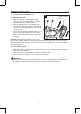
OPERATING INSTRUCTIONS 4. Holding the String Trimmer 4 WARNING • Dress properly to reduce the risk of injury when operating this tool. Do not wear loose clothing or jewelry. Wear eye and ear/hearing protection. Wear heavy, long pants, boots and gloves. Do not wear short pants or sandals or go barefoot. Before operating the unit, stand in the operating position and check that: • The operator is wearing eye protection and proper clothing.
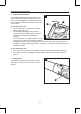
OPERATING INSTRUCTIONS 6. Using the String Trimmer Check for damaged/worn parts before each use 6a Direction of rotation WARNING • To prevent serious personal injury, remove the battery pack from the tool before servicing, cleaning, changing attachments or removing material from the unit. Check the bump head, guard (J) and front-assist handle (G) and replace any parts that are cracked, warped, bent, or damaged in any away. The line-cutting blade (K) on the edge of the guard can dull over time.
OPERATING INSTRUCTIONS • Slowly move the trimmer into and out of the area being cut, maintaining the cutting head position at the desired cutting height. This movement can be either a forward-backward motion or a side-to-side motion. Cutting shorter lengths produces best results. • Trim only when grass and weeds are dry. • Wire and picket fences can cause extra string wear or breakage. Stone and brick walls, curbs, and wood may wear strings rapidly. • Avoid trees and shrubs.
OPERATING INSTRUCTIONS 7. Line Replacement NOTICE: Always use triangle-shaped twisted nylon cutting line with a size that does not exceed 0.08 in. (2.0 mm). Using line other than that specified may cause the string trimmer to overheat or become damaged. 7a WARNING • Never use metal-reinforced line, wire, or rope, etc. These can break off and become dangerous projectiles.
OPERATING INSTRUCTIONS h. Align the notches of the spool from which the lines protrude with the eyelets in the spool retainer and position the spool in the retainer (Fig. 7d). i. Holding the spool and spool retainer, grasp one end of the line and pull it to release the line from the notch in the eyelet (Fig. 7e). Repeat with the other end. j.
CARE AND MAINTENANCE All maintenance should only be carried out by a qualified service technician. Before cleaning or performing any maintenance, remove battery from the tool. For safe and proper operation, always keep the tool and its ventilation slots clean. Cleaning Always use only a soft, dry cloth to clean your string trimmer; never use detergent or alcohol. Clear any grass that may have wrapped itself around the motor shaft or trimmer head. Keep the air vents free of obstructions.
WARRANTY For 5 years from the date of purchase, this product is warranted for the original purchaser to be free from defects in material and workmanship. This guarantee does not cover damage due to abuse, normal wear, improper maintenance, neglect, unauthorized repair/alteration, or expendable parts and accessories expected to become unusable after a reasonable period of use. This warranty is limited to 90 days for commercial and rental use.
18
ARTÍCULO NO. 0726980/0726983/0856456/0856457 ORILLADORA SIN CEPILLO MODELO #KST 1224B-03 ADJUNTE SU RECIBO AQUÍ Número de serie Fecha de compra ¿Preguntas, problemas, piezas faltantes? Antes de volver a la tienda, llame a nuestro Departamento de Servicio al Cliente al 1-888-3KOBALT (1-888-356-2258), de lunes a viernes de 8 a.m. a 8 p.m., hora estándar del Este.
ÍNDICE Especificaciones del producto......................................................................... 20 Contenido del paquete.................................................................................... 21 Información de seguridad................................................................................ 22 Preparación..................................................................................................... 25 Instrucciones de ensamblaje.......................................
CONTENIDO DEL PAQUETE C A B D E H F PIEZA G I K DESCRIPCIÓN J PIEZA DESCRIPCIÓN A Botón de bloqueo-apagado G Manija delantera B Interruptor de gatillo de velocidad variable H Palanca de ajuste C Manija posterior I Perilla con tornillo D Eje de la orilladora J Protector E Cabezal de orilladora K Hoja para corte de hilo F Perilla para golpeteo L Tornillos (2) L ADVERTENCIA • Retire la herramienta del paquete y examínela con cuidado.
INFORMACIÓN DE SEGURIDAD Lea y comprenda completamente este manual antes de intentar ensamblar u operar este producto. Si tiene preguntas relacionadas con el producto, llame al departamento de servicio al cliente al 1-888-3KOBALT, de lunes a viernes de 8 a. m. a 8 p.m., hora estándar del Este. ADVERTENCIA • La operación de cualquier herramienta eléctrica puede arrojar objetos extraños a sus ojos y, de esta manera, causar graves daños oculares.
INFORMACIÓN DE SEGURIDAD Algunos de los siguientes símbolos pueden aplicarse al uso de esta herramienta. Obsérvelos y aprenda su significado. La interpretación correcta de estos símbolos le permitirá utilizar la herramienta de manera eficaz y segura. SÍMBOLO DEFINICIÓN SÍMBOLO DEFINICIÓN V Voltios n Velocidad sin carga A Amperios RPM Revoluciones por minuto Hz Hertz Corriente continua ADVERTENCIA: Para reducir el riesgo de lesiones, el usuario debe leer el manual de instrucciones.
INFORMACIÓN DE SEGURIDAD • Esté alerta: preste atención a lo que está haciendo. Use el sentido común. No use el electrodoméstico si está cansado. • Mantenga los protectores en su lugar y en buenas condiciones de funcionamiento. • Mantenga las manos y los pies alejados del área de corte.
INFORMACIÓN DE SEGURIDAD • Daños en la orilladora: si la orilladora choca con un objeto extraño o si se enreda, detenga la herramienta inmediatamente, verifique que no haya daños y repare los daños que haya antes de intentar volver a utilizarla. No utilice la herramienta si el protector o el carrete está dañado. • Si el equipo comienza a vibrar de manera anormal, detenga el motor y busque la causa de inmediato. Por lo general, la vibración advierte un problema.
INSTRUCCIONES DE ENSAMBLAJE Este producto requiere de ensamblado. Para reducir el riesgo de lesiones a personas, no use la herramienta si los protectores no están en su lugar. El protector siempre debe estar en la herramienta para proteger al usuario. 1. Montaje del protector 1a J ADVERTENCIA • Siempre use guantes cuando monte o reemplace el protector. Tenga cuidado con la hoja del protector y evite que sus manos se lesionen con la hoja.
INSTRUCCIONES DE ENSAMBLAJE 2. Montaje de la manija delantera 2a H ADVERTENCIA • Siempre retire el paquete de baterías del producto cuando no esté en uso o cuando esté ensamblando las piezas, realizando ajustes o limpiándolo. a. Retire el paquete de baterías (no incluido) de la orilladora. B. Retire la perilla del tornillo (I) y la palanca de ajuste (H) de la manija delantera (G). c.
INSTRUCCIONES DE ENSAMBLAJE 3. Cómo fijar y retirar el paquete de baterías Para fijar el paquete de baterías a. Asegúrese de que el interruptor esté en la posición OFF. b. Alinee la parte elevada del paquete de baterías (no incluido) con las ranuras de la parte inferior de la herramienta y luego deslice el paquete de baterías sobre la herramienta, como lo muestra la imagen. c.
INSTRUCCIONES DE FUNCIONAMIENTO 4. Cómo sostener la orilladora 4 ADVERTENCIA • Use ropa adecuada para reducir el riesgo de lesiones cuando use esta herramienta. No use ropa holgada ni joyas. Use protección para los ojos y las orejas. Use pantalones largos y pesados, botas y guantes. No use pantalones cortos ni sandalias, ni tenga los pies descalzos. Antes de usar la unidad, colóquese en la posición de operación y verifique lo siguiente: • El operador usa lentes de protección y ropa adecuada.
INSTRUCCIONES DE FUNCIONAMIENTO 6. Uso de la orilladora 6a Cómo verificar si hay piezas dañadas o desgastadas antes de cada uso Dirección de la rotación ADVERTENCIA • Para evitar lesiones personales graves, retire el paquete de baterías de la herramienta antes de realizarle mantenimiento, limpiarla, cambiarle accesorios o retirarle materiales de la unidad.
INSTRUCCIONES DE FUNCIONAMIENTO • La altura de corte se determina según la distancia del hilo de corte a la superficie del césped. • El césped de más de 8 pulgadas (200 mm) debe cortarse desde la parte superior hacia la inferior en pequeños incrementos para evitar el desgaste prematuro del hilo o el arrastre del motor. • Mueva la orilladora lentamente dentro y fuera del área que se corta manteniendo la posición del cabezal de corte en la altura de corte deseada.
INSTRUCCIONES DE FUNCIONAMIENTO 7. Reemplazo de hilo AVISO: Siempre use hilo de corte de nailon torcido triangular de un tamaño que no supere las 0,08 pulgadas (2 mm). El uso de hilos diferentes de los especificados puede ocasionar que la orilladora se sobrecaliente o se dañe. 7a ADVERTENCIA • No use hilo reforzado con metal, alambre ni cuerda, etc. Estos materiales pueden romperse y convertirse en proyectiles peligrosos.
INSTRUCCIONES DE FUNCIONAMIENTO h. Alinee las muescas del carrete de donde sobresalen los hilos con los ojales del retenedor del carrete y ubique el carrete en el retenedor (Fig. 7d). i. Sosteniendo el carrete y el retenedor del carrete, sujete un extremo del hilo y jálelo para liberar el hilo de la muesca del ojal (Fig. 7e). Repita la operación con el otro extremo. j.
CUIDADO Y MANTENIMIENTO Todas las tareas de mantenimiento deben estar a cargo únicamente de un técnico de servicio calificado. Antes de limpiar o realizar cualquier mantenimiento, retire la batería de la herramienta. Para un uso seguro y adecuado, siempre mantenga limpias la herramienta y sus ranuras de ventilación. Limpieza Use siempre solo un paño suave y seco para limpiar la orilladora; no use detergente ni alcohol. Limpie el pasto que pueda cubrir el eje del motor o el cabezal de la orilladora.
SOLUCIÓN DE PROBLEMAS ADVERTENCIA: • Coloque el interruptor en la posición OFF y retire el paquete de baterías de la herramienta antes de realizar cualquier procedimiento de solución de problemas. PROBLEMA CAUSA POSIBLE ACCIÓN CORRECTIVA La herramienta no funciona. La capacidad de la batería es baja. Cargue el paquete de baterías. La orilladora se detiene mientras se corta. 1. E l eje del motor o el cabezal de la orilladora están atascados con césped. 1.