ITEM #1076663 80 V SNOW THROWER MODEL #KSB 5080-06 Español p. 21 ATTACH YOUR RECEIPT HERE Serial Number Purchase Date Questions, problems, missing parts? Before returning to your retailer, call our customer service department at 1-888-3KOBALT (1-888-356-2258), 8 a.m. - 8 p.m., EST, Monday - Friday.
TABLE OF CONTENTS Product Specifications ������������������������������������������������������������������������������������������������� 2 Package Contents ������������������������������������������������������������������������������������������������������� 3 Hardware Contents ������������������������������������������������������������������������������������������������������ 4 Symbols ���������������������������������������������������������������������������������������������������������������������
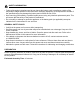
PACKAGE CONTENTS I L G K D E C M H S A F B T Q U O J R P N PART DESCRIPTION A Middle handle PART DESCRIPTION M Chute deflector B Quick-release lever N Scraper C Upper handle O Drive belt cover D Chute-rotation box P Auger pulley E Switch box Q Drive Belt F Discharge chute R Impeller G Battery compartment cover S Speed switch H Safety switch button T Wheels I Bail lever U Skid plates J LED lights V Battery K Light switch W Charger L Chute-rotation h
HARDWARE CONTENTS (not shown actual size) AA BB Handle bolts Handle knobs Qty. 2 Qty. 2 CC EE Chute-rotation box screw nuts Qty. 2 4 DD Chute-rotation box screws Discharge chute screws Qty. 2 Qty.
SYMBOLS Some of the following symbols may be used on this product. Please study them and learn their meaning. Proper interpretation of these symbols will allow you to operate the product better and safer.
SYMBOLS The following signal words and meanings are intended to explain the levels of risk associated with this product. SYMBOL SIGNAL DANGER WARNING CAUTION CAUTION MEANING Indicates an imminently hazardous situation, which, if not avoided, will result in death or serious injury. Indicates a potentially hazardous situation, which, if not avoided, could result in death or serious injury. Indicates a potentially hazardous situation, which, if not avoided, may result in minor or moderate injury.
SAFETY INFORMATION WARNING Read and understand all instructions before using this product. Failure to follow all instructions listed below may result in electric shock, fire, and/or serious personal injury. The term “power tool” in all of the warnings listed below refers to your mains-operated (corded) power tool or battery-operated (cordless) power tool. • Walk. Do not run. • Verify that the power tool is not in contact with anything before turning it on. • Stay away from impeller openings at all times.
SAFETY INFORMATION • Operation of the power tool in the hand-held position is unsafe, except in accordance with the special instructions for such use provided in the operator’s manual. • Keep guards in place and in working order. • Don’t Force Power Tool – It will perform better and safer at the rate for which it was designed. • Don’t Overreach – Keep proper footing and balance at all times. • If the power tool strikes a foreign object, follow these steps: i) Stop the power tool. Release the switch.
SAFETY INFORMATION • Follow all charging instructions and do not charge the battery pack or appliance outside of the temperature range specified in the instructions. Charging improperly or at temperatures outside of the specified range may damage the battery and increase the risk of fire. • Have servicing performed by a qualified repair person using only identical replacement parts. This will ensure that the safety of the product is maintained.
ASSEMBLY INSTRUCTIONS • • WARNING Do not allow familiarity with this product to make you careless. Remember that a careless fraction of a second is sufficient to inflict serious injury. Do not use any attachments or accessories not recommended by the manufacturer of this product. The use of attachments or accessories not recommended can result in serious personal injury. 1. UNFOLDING THE MIDDLE HANDLE • Open the quick-release levers (B) on the two sides of the middle handle (A).
ASSEMBLY INSTRUCTIONS 3. INSTALLING THE CHUTE-ROTATION BOX 3 • Align the holes in the panel of the chute-rotation box (D) and the switch box (E). • Put the chute-rotation box screws (CC) through the holes. • Tighten the chute-rotation box screw nuts (EE) with a wrench (not included). CC D E EE 4. INSTALLING THE DISCHARGE CHUTE • 4 Align the grooves of the discharge chute (F) with the slot on the chute housing. DD • Push the discharge chute into position.
ASSEMBLY INSTRUCTIONS WARNING Always remove battery from your tool when you are assembling parts, making adjustments, cleaning, or when not in use. Removing battery will prevent accidental starting that could cause serious personal injury. 5a. TO INSTALL BATTERY PACK • • • • • Open the battery compartment cover (G). Align the battery (V) with the cavity in the snow thrower housing. Insert the battery into the right battery compartment when standing in the operating position to start the snow thrower.
OPERATING INSTRUCTIONS 1a. POWERING ON Solution 1: 1. Press and hold the safety switch button (H). 2. Pull the bail lever (I) upward to the handle to start the snow thrower and then release the button. Solution 2: 1. Pull the bail lever (I) upward to the handle and hold it. 2. Press the safety switch button (H) to start the snow thrower and release the button. 1b. POWERING OFF • Release the bail lever (I).
OPERATING INSTRUCTIONS 2. LED LIGHTS 2 • To turn on the LED lights (J) for night time snow removal, press the light switch (K). • To turn off the LED lights, press the light switch again. J 3. SPEED SWITCH S • Press the speed switch (S) towards the rabbit symbol for higher impeller speed and discharge distance in heavy conditions. • Press the speed switch (S) towards the turtle system to decrease the impeller speed for greater runtime in light conditions. 4.
OPERATING INSTRUCTIONS 5. ADJUSTING THE CHUTE DEFLECTOR You can adjust the chute deflector (M) up and down to change the throwing distance of the snow. • Squeeze and hold the trigger on the chute deflector. • Move the chute deflector up to increase the snow distance. • Move the chute deflector down to decrease the snow distance. 5 Trigger M OPERATING TIPS WARNING If the snow thrower hits a foreign object while it is in use, the object could be thrown in the direction of the operator or a bystander.
CARE AND MAINTENANCE IMPORTANT: Always remove the battery from the tool before performing any maintenance on it. 1. REPLACING THE SCRAPER NOTE: The scraper is located at the bottom of the impeller housing. Ensure that the battery is not installed in the tool. • Turn the machine to its side. • Remove the 5 bolts below the deck that attach the scraper to the machine. • Remove the worn scraper (N) from the machine. • Install the new scraper. • Install and tighten the bolts that you removed.
CARE AND MAINTENANCE 3. REPLACING THE IMPELLER • Remove the 4 sets of nuts and bolts on the middle steel plate. • Remove the 4 sets of nuts and bolts on each side. • Remove the impellers (R). • Install the new impellers. • Tigthen the 8 sets of nuts and bolts that you removed. 3 R 4 sets of nuts and bolts on the middle steel plate 4 sets of bolts and nuts on each side (total of 8 sets) 4.
TROUBLESHOOTING If you still have questions or an unresolved issue after going through this troubleshooting guide, or just want to speak to a Kobalt product expert, please call our Kobalt customer service department at 1-888-356-2258. PROBLEM The handle is not in position. POSSIBLE CAUSE 1. The bolts are not properly seated. CORRECTIVE ACTION 1. M ake sure the bolts are correctly installed through the handle bars. Check to see if the hand knobs are tight.
WARRANTY 5-YEAR LIMITED WARRANTY This 80 V Lithiuim-Ion snow thrower is warranted to the original purchaser from the original purchase date for five (5) years subject to the warranty coverage described herein. This 80 V Lithiuim-Ion snow thrower is warranted for the original user to be free from defects in material and workmanship.
REPLACEMENT PARTS LIST For replacement parts, call our customer service department at 1-888-356-2258.
ARTÍCULO #1076663 EQUIPO QUITANIEVE DE 80 VOLTIOS MODELO #KSB 5080-06 ADJUNTE SU RECIBO AQUÍ Número de serie Fecha de compra ¿Preguntas, problemas, piezas faltantes? Antes de volver a la tienda, llame a nuestro Departamento de Servicio al Cliente al 1-888-3KOBALT (1-888-356-2258), de lunes a viernes de 8 a.m. a 8 p.m. (hora del este).
ÍNDICE Especificaciones del producto ����������������������������������������������������������������������������������� 22 Contenido del paquete ���������������������������������������������������������������������������������������������� 23 Aditamentos ��������������������������������������������������������������������������������������������������������������� 24 Símbolos ������������������������������������������������������������������������������������������������������������������� 25 Información d
CONTENIDO DEL PAQUETE I L G K D E C M H S A F B T Q U O J R PIEZA A B C D E F G H I J K L P N DESCRIPCIÓN Manija central Palanca de liberación rápida Manija superior Caja de rotación del conducto Caja del interruptor Canal de descarga Cubierta del compartimiento de baterías Botón del interruptor de seguridad Libere la palanca Luz LED Interruptor de luz Manija de rotación del conducto PIEZA DESCRIPCIÓN M Deflector del canal N Raspador O P Q R S T U V W 23 Cubierta de la correa de transmis
ADITAMIENTOS (no se muestran en el tamaño real) AA BB Pernos de la manija Perillas de la manija Cantidad: 2 Cantidad: 2 CC DD Tornillos de la caja de rotación del conducto Tornillos del conducto de descarga Cantidad: 2 Cantidad: 3 EE Tuercas para tornillos de la caja de rotación del conducto Cantidad: 2 24
SÍMBOLOS Algunos de los siguientes símbolos pueden ser usados en este producto. Obsérvelos y aprenda su significado. La interpretación correcta de estos símbolos permite una operación mejor y más segura.
SÍMBOLOS Las siguientes palabras de señalizacion y sus significados tienen el objeto de explicar los niveles de riesgo relaciondos con este producto. SÍMBOLO SEÑAL PELIGRO ADVERTENCIA PRECAUCIÓN PRECAUCIÓN SIGNIFICADO Indica una situación de peligro inminente que, si no es prevenida, causará la muerte o lesiones severas. Indica una situación de peligro potencial que, si no es prevenida, podría causar la muerte o lesiones severas.
INFORMACIÓN DE SEGURIDAD ADVERTENCIA Lea y asegúrese de comprender todas las instrucciones antes de usar este producto. Si no se siguen todas las instrucciones mencionadas a continuación, pudieran producirse descargas eléctricas, incendios y/o lesiones severas. El término “herramienta eléctrica” empleado en todos los avisos de advertencia enumerados abajo se refiere a las herramientas eléctricas de cordón (alámbricas) y de baterías (inalámbricas). • Camine. No corra.
INFORMACIÓN DE SEGURIDAD • Mantenga a los niños alejados: todas las visitas deben mantenerse a una distancia segura del área de trabajo. • Use ropa adecuada: no use ropa holgada ni joyas. Pueden quedar atrapadas en las piezas móviles. • Use botas de goma cuando utilice la herramienta eléctrica. No use el equipo si está descalzo o está usando sandalias abiertas. Siempre use un calzado resistente.
INFORMACIÓN DE SEGURIDAD • Cuando el paquete de baterías no está en uso, aléjelo de objetos metálicos, como sujetapapeles, monedas, llaves, clavos, tornillos u otros objetos metálicos pequeños que pudieran crear una conexión entre los terminales. Es posible que conectar los terminales de la batería entre sí produzca quemaduras o un incendio. • En condiciones de maltrato, es posible que salga líquido de la batería. Evite el contacto. Si se produce un contacto accidental, enjuague con agua.
INSTRUCCIONES PARA EL ENSAMBLAJE • • ADVERTENCIA No permita que la familiaridad con este producto lo vuelva descuidado. Recuerde que un descuido de una fracción de segundo es suficiente para provocar lesiones graves. No utilice ningún acoplamiento o accesorio que no sea recomendado por el fabricante de este producto. El uso de acoplamientos o accesorios no recomendados puede producir lesiones personales graves. 1.
INSTRUCCIONES PARA EL ENSAMBLAJE 3. INSTALACIÓN DE LA CAJA DE ROTACIÓN DEL CONDUCTO • Alinee los orificios en el panel de la caja de rotación del conducto (D) y la caja del interruptor (E). • Coloque los tornillos de la caja de rotación del conducto (CC) en los orificios. • Apriete las tuercas para tornillos de la caja de rotación del conducto (EE) con una llave inglesa (no se incluye). 3 CC D E EE 4.
INSTRUCCIONES PARA EL ENSAMBLAJE ADVERTENCIA Siempre retire el paquete de baterías de la herramienta cuando no esté en uso o cuando esté ensamblando las piezas, realizando ajustes o limpiándolo. La extracción de la batería evitará que se produzca un arranque accidental, lo que podría causar graves lesiones personales. 5a. PARA INSTALAR LA BATERÍA • • • • • Levante la tape (G) del compartimiento de la batería. Alinee la batería (V) con la cavidad de la carcasa del equipo quitanieve.
INSTRUCCIONES DE USO 1a. ENCENDIDO Solución 1: 1. Mantenga presionado el botón del interruptor de seguridad (H). 2. Jale la palanca de agarre (I) hacia arriba de la manija para arrancar el equipo quitanieve y luego suelte el botón. Solución 2: 1. Jale la palanca de agarre (I) hacia debajo de la manija y sosténgala. 2. Presione el botón del interruptor de seguridad (H) para arrancar el equipo quitanieve y suelte el botón. 1b. APAGADO • Libere la palanca (I).
INSTRUCCIONES DE USO 2. LUCES LED • Para encender las luces LED (J) para quitar nieve de noche, presione el interruptor de luz (K). • Para apagar las luces LED, presione el interruptor de luz nuevamente. 2 K J 3. INTERRUPTOR DE VELOCIDAD S • Presione el interruptor de velocidad (S) hacia el símbolo del conejo para mayor velocidad del impulsor y distancia de descarga en condiciones intensas.
INSTRUCCIONES DE USO 5. AJUSTE DEL DEFLECTOR DEL CONDUCTO Puede ajustar el deflector del conducto (M) hacia arriba o hacia abajo para cambiar la distancia de soplado de nieve. • Mantenga presionado el gatillo del deflector del conducto. • Mueva el deflector del conducto hacia arriba para aumentar la distancia de la nieve. • Mueva el deflector del conducto hacia abajo para disminuir la distancia de la nieve.
INSTRUCCIONES DE USO • • • Cuando trabaje sobre guijarros, gravilla o superficies no pavimentadas, evite arrojar materiales sueltos de la superficie junto con la nieve presionando la manija hacia abajo o ajustando las zapatas para elevar el raspador en la base de la unidad por sobre los guijarros o la gravilla. Funcionamiento en climas fríos: Las baterías de iones de litio se pueden usar de manera segura en temperaturas que varían entre 4 °C (39 °F) y 40 °C (104 °F).
CUIDADO Y MANTENIMIENTO IMPORTANTE: siempre retire la batería de la herramienta antes de realizar cualquier tarea de mantenimiento. 1. REEMPLAZO DEL RASPADOR 1 NOTA: el raspador se ubica en la parte inferior de la carcasa del impulsor. Asegúrese de que la batería no esté instalada en la herramienta. • Ponga la máquina de lado. • Retire los 5 pernos debajo de la plataforma que fijan el raspador a la máquina. • Retire el raspador gastado (N) de la máquina. • Instale el raspador nuevo.
CUIDADO Y MANTENIMIENTO 3. REEMPLAZO DEL IMPULSOR • Retire los 4 conjuntos de tuercas y pernos en la placa de acero central. • Retire los 4 conjuntos de tuercas y pernos de cada lado. • Retire los impulsores (R). • Instale los impulsores nuevos. • Apriete los 8 conjuntos de tuercas y pernos que retiró. 3 R 4 conjuntos de tuercas y pernos en la placa de acero central 4 juegos de pernos y tuercas en cada lado (total de 8 juegos) 4.
SOLUCIÓN DE PROBLEMAS Si continua teniendo dudas o algún otro asunto sin resolver tras haber consultado esta guía de resolución de problemas o simplemente desea hablar con un experto en productos Kobalt, llame al servicio de atención al cliente de Kobalt al 1-888-356-2258. PROBLEMA La manija no está en su posición. CAUSA POSIBLE 1. L os pernos de soporte no están apropiadamente asentados. ACCIÓN CORRECTIVA 1. Asegúrese de que los pernos están correctamente instalados en los mangos.
GARANTÍA GARANTÍA DE REPARACIÓN DE 5 AÑOS Este equipo quitanieve de iones de litio de 80 voltios está garantizado para el comprador original desde la fecha de compra original durante cinco (5) años y está sujeto a la cobertura de garantía que aquí se describe. Este equipo quitanieve de iones de litio de 80 voltios tiene una garantía para el usuario original contra defectos en los materiales y la mano de obra.
LISTA DE PIEZAS DE REPUESTO Para encargar piezas de repuesto, llame a nuestro Departamento de Servicio al Cliente al 1-888-356-2258.