ITEM #1319250 80 V SNOW THROWER MODEL #KSB 6080-06 Español p. 21 ATTACH YOUR RECEIPT HERE Serial Number Purchase Date Questions, problems, missing parts? Before returning to your retailer, call our customer service department at 1-888-3KOBALT (1-888-356-2258), 8 a.m. - 8 p.m., EST, Monday - Friday.
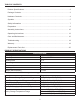
TABLE OF CONTENTS Product Specifications ������������������������������������������������������������������������������������������������� 2 Package Contents ������������������������������������������������������������������������������������������������������� 3 Hardware Contents ������������������������������������������������������������������������������������������������������ 4 Symbols ���������������������������������������������������������������������������������������������������������������������
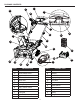
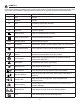
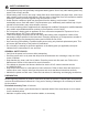
PACKAGE CONTENTS I L G K D E C M H S A F B T Q U O J R P N PART DESCRIPTION A Middle handle PART DESCRIPTION M Chute deflector B Quick-release lever N Scraper C Upper handle O Drive belt cover D Chute-rotation box P Auger pulley E Switch box Q Drive Belt F Discharge chute R Impeller G Battery compartment cover S Speed switch H Safety switch button T Wheels I Bail lever U Skid plates J LED lights V Battery K Light switch W Charger L Chute-rotation h
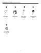
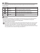
HARDWARE CONTENTS (not shown actual size) AA BB Handle bolts Handle knobs Qty. 2 Qty. 2 CC EE Chute-rotation box screw nuts Qty. 2 4 DD Chute-rotation box screws Discharge chute screws Qty. 2 Qty.
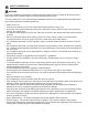
SYMBOLS Some of the following symbols may be used on this product. Please study them and learn their meaning. Proper interpretation of these symbols will allow you to operate the product better and safer.
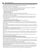
SYMBOLS The following signal words and meanings are intended to explain the levels of risk associated with this product. SYMBOL SIGNAL DANGER WARNING CAUTION CAUTION MEANING Indicates an imminently hazardous situation, which, if not avoided, will result in death or serious injury. Indicates a potentially hazardous situation, which, if not avoided, could result in death or serious injury. Indicates a potentially hazardous situation, which, if not avoided, may result in minor or moderate injury.
SAFETY INFORMATION WARNING Read and understand all instructions before using this product. Failure to follow all instructions listed below may result in electric shock, fire, and/or serious personal injury. The term “power tool” in all of the warnings listed below refers to your mains-operated (corded) power tool or battery-operated (cordless) power tool. • Walk. Do not run. • Verify that the power tool is not in contact with anything before turning it on. • Stay away from impeller openings at all times.
SAFETY INFORMATION • Operation of the power tool in the hand-held position is unsafe, except in accordance with the special instructions for such use provided in the operator’s manual. • Keep guards in place and in working order. • Don’t Force Power Tool – It will perform better and safer at the rate for which it was designed. • Don’t Overreach – Keep proper footing and balance at all times. • If the power tool strikes a foreign object, follow these steps: i) Stop the power tool. Release the switch.
SAFETY INFORMATION • Use appliances only with specifically designated battery packs. Use of any other battery packs may create a risk of injury and fire. • When battery pack is not in use, keep it away from other metal objects, like paper clips, coins, keys, nails, screws or other small metal objects, that can make a connection from one terminal to another. Shorting the battery terminals together may cause burns or a fire. • Under abusive conditions, liquid may be ejected from the battery; avoid contact.
ASSEMBLY INSTRUCTIONS • • WARNING Do not allow familiarity with this product to make you careless. Remember that a careless fraction of a second is sufficient to inflict serious injury. Do not use any attachments or accessories not recommended by the manufacturer of this product. The use of attachments or accessories not recommended can result in serious personal injury. 1. INSTALLING THE CAM LOCK • Remove the knob and spacer from the cam lock. • Insert the bolt through the lower handle housing.
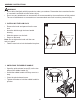
ASSEMBLY INSTRUCTIONS 3. INSTALLING THE UPPER HANDLE • 3 Align the holes on the middle handle (A) and the upper handle (C). Insert the handle bolts (AA) and use the handle knobs (BB) to tighten them. C AA AA 4. INSTALLING THE CHUTE-ROTATION BOX 4 • Align the holes in the panel of the chute-rotation box (D) and the switch box (E). • Put the chute-rotation box screws (CC) through the holes. • Press chute-rotation box screw nuts (EE) under the chute-rotation box (D).
5. INSTALLING THE DISCHARGE CHUTE • 5 Align the grooves of the discharge chute (F) with the slot on the chute housing. DD • Push the discharge chute into position. • Tighten the discharge chute screws (DD) with a Phillips head screw driver to lock the discharge chute. Groove F Slot WARNING Always remove battery from your tool when you are assembling parts, making adjustments, cleaning, or when not in use. Removing battery will prevent accidental starting that could cause serious personal injury.
OPERATING INSTRUCTIONS 1a. POWERING ON Solution 1: 1. Press and hold the safety switch button (H). 2. Pull the bail lever (I) upward to the handle to start the snow thrower and then release the button. Solution 2: 1. Pull the bail lever (I) upward to the handle and hold it. 2. Press the safety switch button (H) to start the snow thrower and release the button. 1b. POWERING OFF • Release the bail lever (I).
OPERATING INSTRUCTIONS 2. LED LIGHTS 2 • To turn on the LED lights (J) for night time snow removal, press the light switch (K). • To turn off the LED lights, press the light switch again. J 3. SPEED SWITCH S • Press the speed switch (S) towards the rabbit symbol for higher impeller speed and discharge distance in heavy conditions. • Press the speed switch (S) towards the turtle system to decrease the impeller speed for greater runtime in light conditions. 4.
OPERATING INSTRUCTIONS 5. ADJUSTING THE CHUTE DEFLECTOR You can adjust the chute deflector (M) up and down to change the throwing distance of the snow. • Squeeze and hold the trigger on the chute deflector. • Move the chute deflector up to increase the snow distance. • Move the chute deflector down to decrease the snow distance. 5 Trigger M OPERATING TIPS WARNING If the snow thrower hits a foreign object while it is in use, the object could be thrown in the direction of the operator or a bystander.
CARE AND MAINTENANCE IMPORTANT: Always remove the battery from the tool before performing any maintenance on it. 1. REPLACING THE SCRAPER NOTE: The scraper is located at the bottom of the impeller housing. Ensure that the battery is not installed in the tool. • Turn the machine to its side. • Remove the 5 nuts below the deck that attach the scraper to the machine. • Remove the worn scraper (N) from the machine. • Install the new scraper. • Install and tighten the nuts that you removed.
CARE AND MAINTENANCE 3. REPLACING THE IMPELLER • Remove the 4 sets of nuts and bolts on the middle steel plate. • Remove the 4 sets of nuts and bolts on each side. • Remove the impellers (R). • Install the new impellers. • Tigthen the 8 sets of nuts and bolts that you removed. 3 R 4 sets of nuts and bolts on the middle steel plate 4 sets of bolts and nuts on each side (total of 8 sets) 4.
TROUBLESHOOTING If you still have questions or an unresolved issue after going through this troubleshooting guide, or just want to speak to a Kobalt product expert, please call our Kobalt customer service department at 1-888-356-2258. PROBLEM The handle is not in position. POSSIBLE CAUSE 1. The bolts are not properly seated. CORRECTIVE ACTION 1. M ake sure the bolts are correctly installed through the handle bars. Check to see if the hand knobs are tight.
WARRANTY 5-YEAR LIMITED WARRANTY This 80 V Lithiuim-Ion snow thrower is warranted to the original purchaser from the original purchase date for five (5) years subject to the warranty coverage described herein. This 80 V Lithiuim-Ion snow thrower is warranted for the original user to be free from defects in material and workmanship.
REPLACEMENT PARTS LIST For replacement parts, call our customer service department at 1-888-356-2258.