ITEM # 1438127 40 V LITHIUM-ION CORDLESS STRING TRIMMER MODEL #KST 4040X-06 Español p. 22 ATTACH YOUR RECEIPT HERE Serial Number Purchase Date Questions, problems, missing parts? Before returning to your retailer, call our customer service department at 1-888-3KOBALT (1-888-356-2258), 8 a.m. - 8 p.m., EST, Monday - Friday.
TABLE OF CONTENTS Product Specifications...........................................................................................................2 Package Contents.................................................................................................................3 Hardware Contents..............................................................................................................4 Symbols................................................................................................
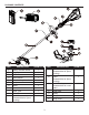
PACKAGE CONTENTS I PART DESCRIPTION A Battery Release Button PART DESCRIPTION M Spool (preassembled to Spool Housing) QUANTITY 1 B Trigger 1 C Lock-off Lever 1 D Speed Switch 1 E Front/Auxiliary Handle 1 F Coupler 1 H Guard 1 I Attachment knob 1 J Upper Tube K L QUANTITY 1 N Eyelet (preassembled to Spool Housing) 1 O Spool Housing (preassembled to Lower Tube) 1 1 P Bump knob 1 Lower Tube 1 Q Battery 1 Spool Cover (preassembled to Spool Housing) 1 R Charger 1
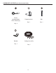
HARDWARE CONTENTS (not shown actual size) Screw (preassembled to the Guard (H)) Fastening Knob Bolt Qty. 1 Qty. 1 Qty. 4 Bracket Cutting Line (10 ft) Qty. 1 Qty.
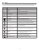
SYMBOLS Some of the following symbols may be used on this product. Please study them and learn their meaning. Proper interpretation of these symbols will allow you to operate the product better and safer. SYMBOLS DESIGNATION V Volts A EXPLANATION Voltage Amperes Current Hz Hertz Frequency (cycles per second) W Watts Power No Load Speed Rotational speed, at no load Alternating Current Type of current Per Minute Revolutions, strokes, surface speed, orbits, etc.
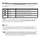
SYMBOLS SAVE THESE INSTRUCTIONS The following signal words and meanings are intended to explain the levels of risk associated with this product. SYMBOL SIGNAL DANGER WARNING CAUTION CAUTION MEANING Indicates an imminently hazardous situation, which, if not avoided, will result in death or serious injury. Indicates a potentially hazardous situation, which, if not avoided, could result in death or serious injury.
SAFETY INFORMATION WARNING Read and understand all instructions. Failure to follow all instructions listed below may result in electric shock, fire, and/or serious personal injury. • Do not operate power tools in explosive atmospheres, such as in the presence of flammable liquids, gases, or dust. Power tools create sparks that may ignite the dust or fumes. • Do not allow children or untrained individuals to use this unit. • Don’t expose power tools to rain or wet conditions.
SAFETY INFORMATION • Do not put any object into openings. Do not use with any opening blocked; keep openings free. • Check the work area before each use. Remove all objects such as rocks, broken glass, nails, wire, or string which can be thrown or become entangled in the machine. • Use only identical manufacturer’s replacement parts and accessories. Use of any other parts may create a hazard or cause product damage. • Do not charge battery in the rain, or damp or wet locations.
SAFETY INFORMATION • Dress Properly – Do not wear loose clothing or jewelry. They can be caught in moving parts. Use of rubber gloves and substantial footwear is recommended when working outdoors. Wear protective hair covering to contain long hair. • Use the Correct Appliance – Do not use appliance for any job except that for which it is intended.
PREPARATION Before beginning assembly of product, make sure all parts are present. Compare parts with package contents list and hardware contents list. If any part is missing or damaged, do not attempt to assemble the product. Estimated Assembly Time: 5 - 10 minutes ASSEMBLY INSTRUCTIONS WARNING To avoid injury and to reduce the risk of electical shock or fire: • Replace the battery or charger immediately if the battery case or charger cord is damaged.
ASSEMBLY INSTRUCTIONS 2. Connect upper/lower trimmer tubes a. Loosen the attachment knob (I) on the coupler. b. Push in the release button located on the lower tube (K). Align the release button with the positioning hole on the upper tube (J) and slide the two tubes together. Rotate the lower tube until the release button locks into the positioning hole. Release button Positioning hole b. Tighten the attachment knob securely.
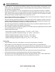
ASSEMBLY INSTRUCTIONS Cutting line A spool of cutting line is pre-installed on the trimmer. When the cutting line needs replacing, rewind new line onto existing spool. CAUTION: To avoid injury, always remove the battery before installing the guard, changing a cutting line, or making any adjustments. 4. To remove the cutting line : a. Remove the battery from the trimmer. b. Turn the string trimmer over to access the spool. c.
ASSEMBLY INSTRUCTIONS 5. To Install the cutting line Note: For 0.080 in. (2.0 mm) nylon line, do not put more than 13 feet of cutting line in at a time. For 0.095 in. (2.4 mm) nylon line, do not put more than 10 feet of cutting line in at a time. a. Remove battery before installing new line. b. Line up the slots on the bump knob (P) with the slots on the spool cover (L). c. Insert line through the eyelet (N). Push line until it exits the opposite string head hole. d.
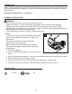
ASSEMBLY INSTRUCTIONS 6. To replace the bump knob 6a a. Remove the battery pack. b. Turn the string trimmer over to access the spool. c. Remove the spool cover (L) by pressing on the two tabs parallel to each other on the sides of the spool cover (L). d. Remove the spool (M) from the spool housing (O). 6b e. While holding the bump knob, firmly pull it out. 6c f. Replace with a new bump knob. Reinstall the spool and spool housing.
ASSEMBLY INSTRUCTIONS 7. Battery IMPORTANT: The battery is not charged when it is purchased. Before using the trimmer for the first time, place the battery in the battery charger and charge. 7. To install: a. Align the battery (Q) with the cavity in the string trimmer housing. b. Insert the battery into the handle until the battery release button (A) locks into place. Push down on the battery until it locks into place. You should hear a “click” once it is installed.
OPERATING INSTRUCTIONS WARNING To avoid injury: • Do not squeeze the trigger while the grass trimmer/edger is inverted. • Do not carry the grass trimmer/edger with your finger on the switch. Avoid unintentional starting. 1. To turn on/off: a. Slide the speed switch (D) to the desired operating speed. Slide the speed switch to position 1 for low speed or position 2 for high speed. b. Press the lock-off lever (C). Squeeze the trigger (B) to start. c. Release the trigger (B) to stop.
OPERATING INSTRUCTIONS Trimmer tips Before each use: • Make sure the protective guard is tightly installed. If not, tighten the guard screws. • Before trimming, inspect the area for string, wire, branches or other material that may become entangled in the cutting line and thrown. Storage tips: • Do not store the grass trimmer/edger in sunlight, in an excessively warm place, or near a furnace. The battery life will be shortened. During use: • Trim only when the grass and weeds are dry.
CARE AND MAINTENANCE Trimmer Guard and Motor Maintenance Note: Before performing maintenance, remove battery from the tool. 1. Remove dirt and debris from guard using a paint brush (not included). 2. Clean line cutter blades by using a wire brush and spraying with an appropriate degreaser. 3. Inspect bump knob and line to ensure that there is an adequate amount of line and that no damage is present on the bump knob.
TROUBLESHOOTING If you still have questions or an unresolved issue after going through this troubleshooting guide, or just want to speak to a Kobalt product expert, please call our customer service department at 1-888-3KOBALT (1-888-356-2258), 8 a.m. - 8 p.m., EST, Monday – Friday. PROBLEM POSSIBLE CAUSE 1. Battery is not secure. 3. Possible wiring or electrical contact problem. CORRECTIVE ACTION 1. To secure the battery, make sure the latches on the battery compartment snap into place. 2.
WARRANTY 5-YEAR LIMITED WARRANTY This Kobalt 40 V String Trimmer is warranted to the original purchaser from the original purchase date for five (5) years subject to the warranty coverage described herein. This Kobalt 40 V String Trimmer is warranted for the original user to be free from defects in material and workmanship.
REPLACEMENT PARTS LIST For replacement parts, call our customer service department at 1-888-3KOBALT (1-888-356-2258), 8 a.m. - 8 p.m., EST, Monday - Friday.