
Use and Care Guide


13
OPERATING INSTRUCTIONS
1. This tool features a torque setting switch (D)
which has two functions:
3
Control the direction of spin: Forward (“F”) to
tighten or Reverse (“R”) to loosen the fastener.
Set the amount of torque applied to the fastener
in the Forward (“F”) position: Settings 1, 2 or 3.
NOTE
Impact wrenches are NOT torque wrenches.
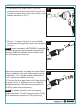
3. To loosen or remove a threaded fastener, push
the switch to the left until it clicks into place over
the “R” indicator. Place the socket over the
threaded fastener on the workpiece, apply
pressure and press the trigger. The tool anvil
will spin counterclockwise to loosen the
threaded fastener up as shown in Fig. 3.
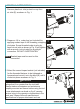
2. To install and tighten a threaded fastener, push
the power regulator switch (D) to the right past
the “F” indicator, until it clicks into place over the
desired setting: the arrow on the switch will point
to the number 1, 2 or 3, and the number will
appear through the hole in the end of the switch.
Place the socket over the threaded fastener on
the workpiece, apply pressure and press the
trigger (C). The tool anvil (B) will spin clockwise
to tighten the threaded fastener down as shown
in Fig. 2.
Fasteners requiring a specific torque must be
checked with an appropriate torque meter after
fitting on the workpiece with an impact wrench.
2
1
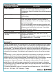
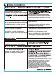
Setting
Torque in Forward (“F”)
Suggested Use
1
Least power to mount
fastener on workpiece
2
Medium power to
tighten fastener
3
Highest power to
tighten fastener
The Forward (“F”) settings 1, 2 and 3 provide
reference torque as shown below. Choose the
correct torque setting to mount fasteners properly
on the workpiece as shown in Fig 1.
190 ft-lb (+/- 10%)
300 ft-lb (+/- 10%)
350 ft-lb (+/- 10%)
The Reverse (“R”) setting ALWAYS operates at maximum
power, as shown below:
R
370 ft-lb (+/- 10%)
Maximum power to remove
fastener from workpiece.