C US 7-1/4-IN COMPACT SLIDING SINGLE-BEVEL MITER SAW MODEL #SM1815LW / #0857240 Français p. 45 Español p. 89 ATTACH YOUR RECEIPT HERE Serial Number MFG Date Purchase Date Questions, problems, missing parts? Before returning to your retailer, call our customer service department at 1-888-3KOBALT (1-888-356-2258), 8 a.m. - 8 p.m., EST, Monday - Friday.
TABLE OF CONTENTS Product Specifications.............................................................................................................. 2 Package Contents..................................................................................................................... 3 General Power Tool Safety Warnings........................................................................................ 4 Safety Information..........................................................................
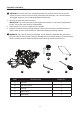
PACKAGE CONTENTS UNPACKING YOUR MITER SAW WARNING: To avoid injury from unexpected starting or electrical shock, do not plug the power cord into a source of power during unpacking and assembly. The cord must remain unplugged whenever you are adjusting/assembling the saw. 1. Remove the miter saw from the carton. IMPORTANT: Do not lift miter saw by the trigger switch handle. It may cause misalignment. Lift the saw by the hand holds for transportation. 2. Place the saw on a secure, stationary work surface. 3.
GENERAL POWER TOOL SAFETY WARNINGS WARNING Read all safety warnings, instructions, illustrations and specifications provided with this power tool. Failure to follow all instructions listed below may result in electric shock, fire and/or serious injury. Save all warnings and instructions for future reference. The term "power tool" in the warnings refers to your mains-operated (corded) power tool or battery-operated (cordless) power tool. Work area safety ● Keep work area clean and well lit.
● Use personal protective equipment. Always wear eye protection. Protective equipment such as dust mask, non-skid safety shoes, hard hat, or hearing protection used for appropriate conditions will reduce personal injuries. ● Prevent unintentional starting. Ensure the switch is in the off-position before connecting to power source and/or battery pack, picking up or carrying the tool. Carrying power tools with your finger on the switch or energising power tools that have the switch on invites accidents.
● Use the power tool, accessories and tool bits etc. in accordance with these instructions, taking into account the working conditions and the work to be performed. Use of the power tool for operations different from those intended could result in a hazardous situation. ● Keep handles and grasping surfaces dry, clean and free from oil and grease. Slippery handles and grasping surfaces do not allow for safe handling and control of the tool in unexpected situations.
● Do not use the saw until the table is clear of all tools, wood scraps, etc., except for the workpiece. Small debris or loose pieces of wood or other objects that contact the revolving blade can be thrown with high speed. ● Cut only one workpiece at a time. Stacked multiple workpieces cannot be adequately clamped or braced and may bind on the blade or shift during cutting. ● Ensure the miter saw is mounted or placed on a level, firm work surface before use.
PROPOSITION 65 WARNING Some dust created by power sanding, sawing, grinding, drilling and other construction activities contains chemicals known to the State of California to cause cancer, birth defects or other reproductive harm. Some examples of these chemicals are: ● ● ● Lead from lead-based paints, Crystalline silica from bricks and cement and other masonry products, and Arsenic and chromium from chemically-treated lumber.
SAFETY INFORMATION ELECTRICAL SPECIFICATIONS AND SAFETY CAUTION: POWER SUPPLY AND MOTOR The A/C motor used in this saw is a universal, nonreversible type. See “MOTOR” in the “PRODUCT SPECIFICATIONS” section on page 2. To avoid electrical hazards, fire hazards or damage to the tool, use proper circuit protection. Your saw is wired at the factory for 120V operation. Connect to a 120V, 10A circuit and use a 15A time-delay fuse or circuit breaker.
● FUSES may “blow” or circuit breakers may trip frequently if: MOTOR is overloaded – overloading can occur if you feed too rapidly or make too many starts/stops in a short time. - LINE VOLTAGE is more than 10% above or below the nameplate voltage rating. For heavy loads, the voltage at motor terminals must equal the voltage specified on the nameplate. - IMPROPER or dull saw blades are used.
PREPARATION Before beginning assembly or operation of the product, make sure all parts are present. Compare parts with package contents list and diagram on page 3. If any part is missing or damaged, do not attempt to assemble, install or operate the product. Estimated Assembly Time: 10 minutes. Tools Required for Assembly (included): Blade Wrench. Tools Required for Assembly (not included): Adjustable Wrench, 6 mm Hex Wrench, 10 mm Wrench, Combination Square, Phillips Screwdriver, Flathead Screwdriver.
KNOW YOUR MITER SAW Switch Handle Laser Guide Motor Brush Upper Blade Guard Motor Slide Carriage Lower Blade Guard Hold-Down Clamp Base Mounting Holes Table Insert Miter Handle Hand Hold for Transportation Positive Miter Stop Laser ON/OFF Switch Cutting Depth Stop Knob Stop Latch Knob Arbor Lock Button Sliding Carriage Lock Knob Blade Bevel Lock Handle Fence Positive Miter Stop Locking Lever Table Hand Hold for Transportation 12 Blade Wrench Storage
ASSEMBLY INSTRUCTIONS WARNING: To avoid injury, do not connect this miter saw to a power source until it is completely assembled and adjusted and you have read and understood the operator’s manual. 1 INSTALLING THE MITER HANDLE (FIG. 1) ● Thread the miter handle (E) into the hole located at the front of the miter saw (A). A E INSTALLING THE DUST BAG (FIG. 2) ● Squeeze the metal collar wings on the dust bag (C).
INSTALLING THE HOLD-DOWN CLAMP (FIG. 3) NOTE: There are two mounting holes for the hold-down clamp. These are located just behind the fence on the left and right side of the base. ● ● ● 3 Loosen the lock knob behind the fence. Place the hold-down clamp (B) in the desired mounting hole. Tighten the lock knob to hold the hold-down clamp. BLADE WRENCH (FIG.
ADJUSTMENT INSTRUCTIONS UNLOCKING THE SLIDE CARRIAGE (FIG. 5) ● After removing the saw from the carton, loosen the slide carriage lock knob (1). When transporting or storing the miter saw, the slide carriage should always be locked in position. The slide carriage lock knob (1) is located on the right side of the slide carriage. 5 UNLOCKING AND LOCKING THE CUTTER HEAD (FIG.
REMOVING AND INSTALLING THE TABLE INSERT (FIG. 7) NOTE: The miter saw comes with the table insert already installed. These instructions are for replacing or adjusting the insert. 7 1 WARNING To avoid injury: ● Always unplug the saw to avoid accidental starting. Remove all small pieces of material from the table cavity before performing any cuts. The table insert may be removed for this purpose, but always reattach the table insert prior to performing a cutting operation.
Mounting instructions: ● For stationary use, place the saw in the desired location, directly on a workbench where there is room for handling and proper support of the workpiece. The base of the saw has eight mounting holes (10 - Fig. 8), four 9/32 in. holes for mounting the saw to the work surface. Bolt the base of the miter saw (1) to the work surface (5), using the recommended fastening method as shown in Fig. 9. NOTE: Mounting hardware is not included with this tool.
REMOVING AND INSTALLING THE BLADE ● ● ● WARNING: Use only a saw blade diameter in accordance with the markings on the saw. Only use 7-1/4 in. diameter crosscut blades on this saw. Do not use blades with deep gullets. These can deflect and contact the guard, and can cause damage to the machine and/or serious injury. To avoid injury from an accidental start, make sure the switch is in the OFF position and the plug is not connected to the power source outlet.
INSTALLING BLADE (FIG. 11, 12, 13) Unplug the miter saw before changing/installing the blade. ● ● ● ● ● ● ● ● ● ● ● 13 Install a 7-1/4 in. blade with a 5/8 in. arbor 9 hole, making sure the rotation arrow on the 7 blade matches the clockwise rotation arrow on the upper guard and the blade teeth are pointing downward at the front of the saw. 6 Place the blade (7) onto the arbor (9) and 4 against the inner blade collar (8).
BEVEL STOP ADJUSTMENT (FIG. 14, 15, 16) 14 WARNING: To avoid injury from an accidental start, make sure the switch is in the OFF position and the plug is not connected to the power source outlet. 1 90° (0°) Bevel Adjustment (Fig. 14): ● Loosen bevel lock handle (1) and tilt the cutting arm completely to the right. Tighten the bevel lock handle. ● Place a combination square (2) on the miter table with the ruler against the table and the heel of the square against the saw blade.
45° Bevel Adjustment (Fig. 16): ● Loosen the bevel lock handle (1) and tilt the cutting head completely to the left. ● Using a combination square, check to see if the blade angle is 45° to the table. ● If the blade is not at 45° to the miter table, tilt the cutting arm to the right, loosen the locknut (2) on the bevel angle adjustment bolt (3) and use a 10 mm wrench to the adjustment bolt (3) depth in or out to increase or decrease the bevel angle.
ADJUSTING FENCE SQUARENESS (FIG. 18) ● Lower the cutting arm and lock in position. ● Loosen the four fence locking bolts (1) with a 6 mm hex wrench. ● Using a square (3), lay the heel of the square against the blade and the ruler against the fence (2) as shown. ● Adjust the fence 90° to the blade and tighten the four fence locking bolts. NOTE: If the saw has not been used recently, recheck blade squareness to the fence and readjust if needed.
TO TURN LASER GUIDE ON (FIG. 20) ● To turn laser on, press on/off rocker switch (1) to “ON” position. ● To turn laser off, press on/off rocker switch (1) to “OFF” position. 20 2 1 ALIGNING THE LASER GUIDE (FIG. 20, 21, 22) The laser line must always be correctly aligned with the blade to ensure straight, even cutting. Your tool is equipped with a laser cutting guide that uses a Class II laser line.
● WARNING: Do not attempt to repair or disassemble the laser. If unqualified persons attempt to repair this laser product, serious injury may result. Any repair required on this laser product should be performed by a qualified service dealer. 22 Cutting line Laser line Workpiece Laser line NOTE: If laser labels are missing, damaged or not clear, contact with the Customer Service Department for replacements. Blade LASER GUIDE ADJUSTMENT (FIG.
● ● ● Slide the cutting head forward enough so that the laser line is visible on the front of the board. Looking at the front of the board, if the laser line is not parallel to the “pattern line” please follow the instructions listed below under “Front Line” paragraph. Looking at the top of the board, if the laser line is not parallel to the “pattern line” please follow the instructions listed below under “Top Line” paragraph. 24 Laser line Clockwise Pattern line Counterclockwise B.
OPERATING INSTRUCTIONS BEFORE USING THE MITER SAW WARNING: To avoid mistakes that could cause serious, permanent injury, do not plug the tool in until the following steps are completed: ● ● ● ● ● Completely assemble and adjust the saw, following the instructions (SEE ASSEMBLY AND ADJUSTMENTS SECTIONS). Learn the use and function of the ON/OFF switch, upper and lower blade guards, stop latch, bevel lock handle and cover plate screws.
KEEP YOUR WORK AREA CLEAN Cluttered areas and benches invite accidents. WARNING: To avoid burns or other fire damage, never use the miter saw near flammable liquids, vapors or gases. ● ● ● Plan ahead to protect your eyes, hands, face and ears. Read and understand the operator’s manual and labels affixed to the tool. Learn its application and limitations as well as the potential hazards specific to this tool.
Never cut freehand: ● Brace your workpiece firmly against the fence and table stop so it will not rock or twist during the cut. ● Make sure there is no debris between the workpiece and the table or fence. Make sure there are no gaps between the workpiece, fence and table that will let the workpiece shift after it is cut. ● Keep the cut piece free to move sideways after it is cut off. Otherwise, it could get wedged against the blade and thrown violently. ● Only the workpiece should be on the saw table.
BODY AND HAND POSITION (FIG. 26) WARNING Never place hands near the cutting area. Proper positioning of your body and hands when operating the miter saw will make cutting easier and safer. Keep children away. Keep all visitors at a safe distance from the miter saw. Make sure bystanders are clear of the saw and workpiece. Do not force the saw. It will do the job better and safer at its designed rate.
BASIC SAW OPERATIONS 27 1 TURNING THE LASER GUIDE ON (FIG. 27) Press the on/off rocker switch (1) to “ON” position to activate the laser guide. 4 TURNING THE SAW ON (FIG. 27) This miter saw is equipped with a two step ON/OFF trigger switch. Press down on the yellow safety lock switch (3) and squeeze the trigger switch (2) to turn the miter saw ON. 3 NOTE: Make the ON/OFF switch childproof.
BEFORE LEAVING THE SAW ● Never leave tool running unattended. Turn power OFF. Wait for all moving parts to stop. ● Make workshop childproof. Lock the shop. Disconnect master switches. Store tool away from children and other unqualified users. 29 WARNING: To avoid injury from materials being thrown, always unplug the saw to avoid accidental starting and remove small pieces of material from the table cavity. 3 MITER CUT (FIG.
COMPOUND CUT (FIG. 31) A compound cut is the combination of a miter and a bevel cut simultaneously. ● Loosen the miter handle (1). Lift up the positive stop locking lever (2) and position the table at the desired angle. Release the positive stop locking lever (2) and lock the miter handle (1). ● Loosen the bevel lock handle (3) and position the cutting head at the desired bevel position. Lock the bevel lock handle (3).
CUTTING BOWED MATERIAL (FIG. 33) A bowed workpiece must be positioned against the fence and secured with a clamp (1) before cutting as shown. Do not position workpiece incorrectly or try to cut the workpiece without the support of the fence. This will cause the blade to bind and could result in personal injury. 33 CUTTING GROOVES (FIG. 34) WARNING: DO NOT USE A DADO BLADE, use only the standard saw blade for this operation.
AUXILIARY WOOD FENCE (FIG. 36) When making multiple or repetitive cuts that result in cut-off pieces of one inch or less, it is possible for the saw blade to catch the cut-off piece and throw it out of the saw or into the blade guard and housing, possibly causing damage or injury. To minimize this, an auxiliary wood fence can be mounted to your saw. Holes are provided in the saw fence to attach an auxiliary wood fence (this provides additional depth of cut).
CUTTING CROWN MOULDING (FIG. 38, 39) Your compound miter saw is suited for the difficult task of cutting crown moulding. To fit properly, crown moulding must be compoundmitered with extreme accuracy. The two surfaces on a piece of crown moulding that fit flat against the ceiling and wall are at angles that, when added together, equal exactly 90°.
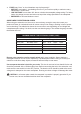
Bevel/Miter Settings NOTE: The chart below references a compound cut for crown moulding ONLY WHEN THE ANGLE BETWEEN THE WALLS EQUALS EXACTLY 90°. KEY BEVEL ANGLE SETTING MITER ANGLE SETTING TYPE OF CUT Inside Corner - Left Side IL 33.9° 31.6° Right 1. Position top of moulding against fence. 2. LEFT side is finished piece. Inside Corner - Right Side IR 33.9° 31.6° Left 1. Position bottom of moulding against fence. 2. LEFT side is finished piece. Outside Corner-Left Side OL 33.9° 31.6° Left 1.
CROWN MOULDING CHART Compound Miter Saw Miter and Bevel Angle Settings Wall to Crown Moulding Angle Angle Between Walls 67 68 69 70 71 72 73 74 75 76 77 78 79 80 81 82 83 84 85 86 87 88 89 90 91 92 93 94 95 96 97 98 99 100 101 102 103 104 105 106 107 108 109 110 111 112 113 114 115 116 117 118 119 120 121 122 52/38° Crown Moulding 45/45° Crown Moulding Miter Setting Bevel Setting Miter Setting Bevel Setting 42.93 42.39 41.85 41.32 40.79 40.28 39.76 39.25 38.74 38.24 37.74 37.24 36.75 36.27 35.79 35.
CARE AND MAINTENANCE ● ● ● WARNING To avoid fire or toxic reaction, never use gasoline, naphtha acetone, lacquer thinner or similar highly volatile solvents to clean the miter saw. To avoid injury from unexpected starting or electrical shock, unplug the power cord before working on the saw. For your safety, this saw is double insulated. To avoid electrical shock, fire or injury, use only parts identical to those identified in the parts list. Reassemble exactly to avoid electrical shock.
SAWDUST Periodically, sawdust will accumulate under the worktable and base. This could cause difficulty in the movement of the worktable when setting up a miter cut. Frequently blow out or vacuum up the sawdust. 41 Central pivot of plastic guard CAUTION If blowing sawdust, wear proper eye protection to keep debris from blowing into eyes. LUBRICATION (FIG.
TROUBLESHOOTING WARNING To avoid injury from accidental starting, always ensure switch is in the OFF position and unplug the tool before moving, replacing the blade or making adjustments. TROUBLESHOOTING – MOTOR PROBLEM POSSIBLE CAUSE Blade does not 1. Motor brushes not sealed or stop within lightly sticking. 10 seconds. 2. Arbor bolt loosened. 3. Other. CORRECTIVE ACTION 1. Inspect, clean and/or replace brushes. See CARE AND MAINTENANCE section. 2. Retighten the arbor bolt. 3. Contact customer service.
REPLACEMENT PARTS LIST For replacement parts, call our customer service department at 1-888-3KOBALT, 8 a.m. - 8 p.m., EST, Monday - Friday. B C PART E D DESCRIPTION F G PART # B Hold-down clamp 3V94 C Dust bag 3W0V D Blade wrench 3VJN E Miter handle 3TBS F Manual 3W0X G Carbon brushes (set of 2) 0QBG DISTRIBUTED BY: L G SOURCING, INC. P.O. BOX 1535 N.
PAGE INTENTIONALLY LEFT BLANK 42
PAGE INTENTIONALLY LEFT BLANK 43
WARRANTY The manufacturer will offer replacement parts for this product which under normal usage have proven to be defective in their manufacture or workmanship for a period of THREE (3) years from the date of initial retail purchase. This warranty is valid only to the original purchaser. This warranty is not transferable and does not cover any parts that have been subjected to misuse, abuse, alteration, overload, accident or normal wear of moving parts.