ITEM #0358937 7-1/4 IN. SLIDING COMPOUND MITER SAW WITH LASER GUIDE R R KOBALT is a registered trademark of LF, LLC. All Rights Reserved. MODEL #SM1850LW Français p. 45 Español p. 89 NOTICE: On the nameplate of the machine you will find the serial number and MFG date code of the unit. Please record these numbers on this manual cover for future service reference.
TABLE OF CONTENTS Product Specifications...................................................................................................................... 2 Package Contents............................................................................................................................ 3 Safety Information............................................................................................................................. 4 Preparation....................................................
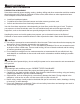
PACKAGE CONTENTS UNPACKING YOUR MITER SAW WARNING: To avoid injury from unexpected starting or electrical shock, do not plug the power cord into a source of power during unpacking and assembly. The cord must remain unplugged whenever you are adjusting/assembling the saw. 1. Remove the miter saw from the carton. IMPORTANT: Do not lift miter saw by the trigger switch handle. It may cause misalignment. Lift the saw by the hand holds for transportation. 2. Place the saw on a secure, stationary work surface. 3.
SAFETY INFORMATION GENERAL SAFETY INFORMATION PROPOSITION 65 WARNING Some dust created by power sanding, sawing, grinding, drilling and other construction activities contains chemicals known to the State of California to cause cancer, birth defects or other reproductive harm. Some examples of these chemicals are: ● ● ● Lead from lead-based paints, Crystalline silica from bricks and cement and other masonry products, and Arsenic and chromium from chemically-treated lumber.
SAFETY INFORMATION POWER TOOL SAFETY Please read and understand this entire manual before attempting to assemble, operate or install the product. These safety instructions are not meant to cover every possible condition that could occur. GENERAL SAFETY INSTRUCTIONS ● LEARN the tool’s application, limitations and possible hazards. ● KEEP GUARDS IN PLACE and in working order. ● REMOVE ADJUSTING KEYS AND WRENCHES.
● MAINTAIN TOOLS WITH CARE. Keep tools sharp and clean for best and safest performance. Follow instructions for lubricating and changing accessories. ● DIRECTION OF FEED. Feed work into a blade or cutter against the direction of rotation of the blade or cutter. CAUTION: Dust generated from certain materials can be hazardous to your health. Always operate the saw in a well-ventilated area and provide for proper dust removal.
● DISCONNECT the saw from the power source and clean the machine when finished using. ● SHOULD any part of your miter saw become missing, damaged, fail in any way or any electrical component fail to perform properly, shut off the switch and remove the plug from the power supply outlet. Replace missing, damaged or failed parts before resuming operation. ● Because of the downward cutting motion, your safety requires that you stay very alert to keeping hands and fingers away from the path that the blade travels.
SAFETY INFORMATION ELECTRICAL SPECIFICATIONS AND SAFETY CAUTION: POWER SUPPLY AND MOTOR The A/C motor used in this saw is a universal, nonreversible type. See “MOTOR” in the “PRODUCT SPECIFICATIONS” section on page 2. To avoid electrical hazards, fire hazards or damage to the tool, use proper circuit protection. Your saw is wired at the factory for 120V operation. Connect to a 120V, 15A circuit and use a 15A time-delay fuse or circuit breaker.
GUIDELINES FOR EXTENSION CORDS When using an extension cord, be sure to use one heavy enough to carry the current your product will draw. An undersized cord will cause a drop in line voltage, resulting in loss of power and overheating. The table below shows the correct size to use depending on cord length and nameplate ampere rating. If in doubt, use the next heavier gauge. The smaller the gauge number, the heavier the cord.
PREPARATION Before beginning assembly or operation of the product, make sure all parts are present. Compare parts with package contents list and diagram on page 3. If any part is missing or damaged, do not attempt to assemble, install or operate the product.
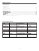
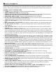
KNOW YOUR MITER SAW Safety Lock Upper Blade Guard Switch Handle Dust Bag Laser Guide Blade Base Hold-Down Clamp Table Insert Fence Hand Hold for Transportation Positive Miter Stop Mounting Hole ON/OFF Trigger Switch Blade Wrench Motor Brush Arbor Lock Button Motor Head Hold-Down Latch Lower Blade Guard Sliding Carriage Lock Knob Table Miter Handle Positive Miter Stop Locking Lever Bevel Locking Handle Bevel Scale K Miter Scale Hand Hold for Transportation 11
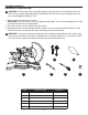
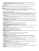
ASSEMBLY INSTRUCTIONS WARNING: To avoid injury, do not connect this miter saw to a power source until it is completely assembled and adjusted and you have read and understood the operator’s manual. 1 INSTALLING THE MITER HANDLE (FIG. 1) ● Thread the miter handle (E) into the hole located at the front of the miter saw (A). INSTALLING THE DUST BAG (FIG. 2) ● Squeeze the metal collar wings on the dust bag (C).
INSTALLING THE HOLD-DOWN CLAMP (FIG. 3) NOTE: There are two mounting holes for the holddown clamp. These are located just behind the fence on the left and right side of the base. ● Loosen the screw with a Phillips screwdriver. ● Place the hold-down clamp (B) in the desired mounting hole. ● Tighten the screw to hold the hold-down clamp. 3 Mounting holes B Screw SAW BLADE WRENCH (FIG.
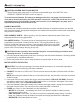
ADJUSTMENT INSTRUCTIONS UNLOCKING THE SLIDE CARRIAGE (FIG. 5) ● After removing the saw from the carton, loosen the slide carriage lock knob (1). When transporting or storing the miter saw, the slide carriage should always be locked in position. The slide carriage lock knob (1) is located on the right side of the slide carriage. 5 1 K KOBALT UNLOCKING AND LOCKING THE CUTTER HEAD (FIG.
REMOVING AND INSTALLING THE TABLE INSERT (FIG. 7) NOTE: The miter saw comes with the table inserts already installed. These instructions are for replacing or adjusting either insert side. WARNING To avoid injury: ● Always unplug the saw to avoid accidental starting. Remove all small pieces of material from the table cavity before performing any cuts. The table insert may be removed for this purpose, but always reattach the table insert prior to performing a cutting operation.
MOUNTING THE MITER SAW (FIG. 8, 9, 10) WARNING To avoid injury from unexpected saw movement: ● Disconnect the power cord from the outlet and lock the cutting head in the lower position using the stop latch. ● Lock the slide carriage in place by tightening the slide carriage lock knob. ● To avoid back injury, lift the saw by using the hand holds for transportation. Bend with your knees, not your back. ● Never carry the miter saw by the power cord or by the switch handle.
REMOVING AND INSTALLING THE BLADE WARNING: Only use a 7-1/4 in. diameter blade. To avoid injury from an accidental start, make sure the switch is in the OFF position and the plug is not connected to the power source outlet. REMOVING (FIG. 11, 12, 13) ● Unplug the saw from the outlet. ● Allow the miter saw cutting head to rise to the upright position. Raise the lower blade guard (1) to the up position. ● Loosen the cover plate screw (2) with a Phillips screwdriver. NOTE: Do not remove this screw.
INSTALLING BLADE (FIG. 11, 12, 13) Unplug the miter saw before changing/installing the blade. 13 7 ● Install a 7-1/4 in. blade with a 5/8 in. arbor, making sure the rotation arrow on the blade matches the clockwise rotation arrow on the upper guard. ● Place the blade collar (6) against the blade and on the arbor. Thread the arbor bolt (4) onto the arbor (Fig. 13) in a counterclockwise direction. IMPORTANT: Make sure the flats of the blade collars are engaged with the flats on the arbor shaft.
BEVEL STOP ADJUSTMENT (FIG. 14, 15, 16) WARNING: To avoid injury from an accidental start, make sure the switch is in the OFF position and the plug is not connected to the power source outlet. 90° (0°) Bevel Adjustment (FIG. 14): ● Loosen bevel lock handle (1) and tilt the cutting arm completely to the right. Tighten the bevel lock handle. ● Place a combination square (2) on the miter table with the ruler against the table and the heel of the square against the saw blade.
MITER SCALE (FIG. 17) The sliding compound miter saw scale can be easily read, showing miter angles from 0° to 45° to the left, and 0° to 45° to the right. The miter saw table has nine of the most common angle settings with positive stops at 0°, 15°, 22.5°, 31.6°, and 45°. These positive stops position the blade at the desired angle quickly and accurately. Follow the process below for quickest and most accurate adjustments.
SETTING CUTTING DEPTH (FIG. 19) The depth of cut can be preset for even and repetitive shallow cuts. ● Adjust the cutting head down until the teeth of the blade are at the desired depth. ● While holding the upper arm in that position, turn the stop knob (1) until it touches the stop plate (2). ● Recheck the blade depth by moving the cutting head front to back through the full motion of a typical cut along the control arm. 19 1 2 MAXIMUM CUTTING DEPTH (FIG.
DANGER: AVOID DIRECT EYE CONTACT ● A red laser line is radiated when the laser guide switch is turned on. Avoid direct eye contact. Always unplug the miter saw from power source before making any adjustments. : M à Puissance Ce produit est conforme aux normes 21CFR 1040.10 et 1040.11 las normas ● Laser Warning Label: Max. output < 5 mW, wavelength: 630-660 nm, complies with 21CFR 1040.10 and 1040.11 Class IIIa laser product. (Fig.
OPERATING INSTRUCTIONS BEFORE USING THE MITER SAW WARNING: To avoid mistakes that could cause serious, permanent injury, do not plug the tool in until the following steps are completed: ● Completely assemble and adjust the saw, following the instructions (SEE ASSEMBLY AND ADJUSTMENTS SECTIONS). ● Learn the use and function of the ON/OFF switch, upper and lower blade guards, stop latch, bevel lock handle and cover plate screws.
KEEP YOUR WORK AREA CLEAN Cluttered areas and benches invite accidents. WARNING: To avoid burns or other fire damage, never use the miter saw near flammable liquids, vapors or gases. ● Plan ahead to protect your eyes, hands, face and ears. ● Read and understand the operator’s manual and labels affixed to the tool. Learn its application and limitations as well as the potential hazards specific to this tool.
Never cut freehand: ● Brace your workpiece firmly against the fence and table stop so it will not rock or twist during the cut. ● Make sure there is no debris between the workpiece and the table or fence. Make sure there are no gaps between the workpiece, fence and table that will let the workpiece shift after it is cut. ● Keep the cut piece free to move sideways after it is cut off. Otherwise, it could get wedged against the blade and thrown violently. ● Only the workpiece should be on the saw table.
BODY AND HAND POSITION (FIG. 23) 23 WARNING Never place hands near the cutting area. Proper positioning of your body and hands when operating the miter saw will make cutting easier and safer. Keep children away. Keep all visitors at a safe distance from the miter saw. Make sure bystanders are clear of the saw and workpiece. Do not force the saw. It will do the job better and safer at its designed rate.
BASIC SAW OPERATIONS 24 4 TURNING THE LASER GUIDE ON (FIG. 24) Press the on/off rocker switch (1) to “ON” position to activate the laser guide. 3 2 TURNING THE SAW ON (FIG. 24) This miter saw is equipped with an ON/OFF trigger switch (2). With the safety lock (3) pressed, squeeze the trigger switch to turn the miter saw ON. 1 OFF ON LASER NOTE: Make the ON/OFF switch childproof.
BEFORE LEAVING THE SAW ● Never leave tool running unattended. Turn power OFF. Wait for all moving parts to stop. ● Make workshop childproof. Lock the shop. Disconnect master switches. Store tool away from children and other unqualified users. 26 WARNING: To avoid injury from materials being thrown, always unplug the saw to avoid accidental starting and remove small pieces of material from the table cavity. MITER CUT (FIG.
COMPOUND CUT (FIG. 28) A compound cut is the combination of a miter and a bevel cut simultaneously. ● Loosen the bevel lock handle (1) and position the cutting head at the desired bevel position. Lock the bevel lock handle (1). ● Loosen the miter handle (2). Lift up the positive stop locking lever (3) and position the table at the desired angle. Release the positive stop locking lever (3) and lock the miter handle (2). 28 1 K SLIDE CUTTING WIDE BOARDS UP TO 8 IN. WIDE (FIG.
CUTTING GROOVES (FIG. 31) WARNING: DO NOT USE A DADO BLADE, use only the standard saw blade for this operation. ● Mark lines to identify the width and depth of the desired cut on the workpiece and put the workpiece on the table and aim the inside tip of the blade at the line. Use a clamp to secure the workpiece on the table. ● Lower the cutting head so the tip of the blade touches the top surface of the workpiece at the marked line.
CUTTING BASE MOULDING (FIG. 34) Base mouldings and many other mouldings can be cut on a compound miter saw. The setup of the saw depends on moulding characteristics and applications, as shown. Perform practice cuts on scrap material to achieve best results: ● Always make sure mouldings rest firmly against the fence and table. Use hold-down or C-clamps, whenever possible, and place tape on the area being clamped to avoid marks. ● Reduce splintering by taping the cut area prior to making cut.
Bevel/Miter Settings BEVEL KEY SETTING Inside corner - Left side IL 33.9° MITER SETTING TYPE OF CUT 31.6° Right 1. Position top of moulding against fence. 2. Miter table set at RIGHT 31.6°. 3. LEFT side is finished piece. 31.6° Left 1. Position bottom of moulding against fence. 2. Miter table set at LEFT 31.6°. 3. LEFT side is finished piece. 31.6° Left 1. Position bottom of moulding against fence. 2. Miter table set at LEFT 31.6°. 3. RIGHT side is finished piece. 31.6° Right 1.
CROWN MOULDING CHART Compound Miter Saw Miter and Bevel Angle Settings Wall to Crown Moulding Angle 52/38° Crown 45/45° Crown Moulding Moulding Angle Miter Bevel Miter Bevel Between Setting Setting Setting Setting Walls 67 68 69 70 71 72 73 74 75 76 77 78 79 80 81 82 83 84 85 86 87 88 89 90 91 92 93 94 95 96 97 98 99 100 101 102 103 104 105 106 107 108 109 110 111 112 113 114 115 116 117 118 119 120 121 42.93 42.39 41.85 41.32 40.79 40.28 39.76 39.25 38.74 38.24 37.74 37.24 36.75 36.27 35.79 35.31 34.
CARE AND MAINTENANCE WARNING ● To avoid fire or toxic reaction, never use gasoline, naphtha acetone, lacquer thinner or similar highly volatile solvents to clean the miter saw. ● To avoid injury from unexpected starting or electrical shock, unplug the power cord before working on the saw. ● For your safety, this saw is double insulated. To avoid electrical shock, fire or injury, use only parts identical to those identified in the parts list. Reassemble exactly to avoid electrical shock.
SAWDUST Periodically, sawdust will accumulate under the worktable and base. This could cause difficulty in the movement of the worktable when setting up a miter cut. Frequently blow out or vacuum up the sawdust. 38 Central pivot of plastic guard CAUTION If blowing sawdust, wear proper eye protection to keep debris from blowing into eyes. LUBRICATION (FIG.
TROUBLESHOOTING WARNING To avoid injury from accidental starting, always ensure switch is in the OFF position and unplug the tool before moving, replacing the blade or making adjustments. TROUBLESHOOTING – MOTOR PROBLEM POSSIBLE CAUSE Blade does not 1. Motor brushes not sealed or lightly stop within 10 sticking. seconds. 2. Arbor bolt loosened. 3. Other. Motor does not start. 1. Blown fuse. 2. Worn brush. 3. Other. 1. Use and check the 15A time-delay fuse or the circuit breaker. 2.
WARRANTY The manufacturer will offer replacement parts for this product which under normal usage have proven to be defective in their manufacture or workmanship for a period of THREE (3) years from the date of initial retail purchase. This warranty is valid only to the original purchaser. This warranty is not transferable and does not cover any parts that have been subjected to misuse, abuse, alteration, overload, accident or normal wear of moving parts.
REPLACEMENT PARTS LIST - SAW (PART A) I.D. X4NP X4P0 X4P1 X4P2 X4P3 X4P4 X4P5 X4P6 X4P7 X4P8 X4P9 X4PA X4PB X4PC X4PD X4PE X4PF X4PG X4PH X4PL X4PP X4PQ X4PR X4PS X4PT X4PU X4PV X4PW X4PX Description Size Q’ty I.D. Description MOTOR ASS’Y 1 X4PY DUST BAG CR. RE. PAN HD. SCREW M5*55 1 X4PZ LASER COVER BATTERY (AAA) 2 X4Q0 LASER LABEL (LEFT) BATTERY BOX 1 X4Q1 CR. RE. COUNT HD. SCREW BUTTON SWITCH 1 X4Q2 ANTI-DUST PLATE CR. RE. PAN HD. TAPPING ST3.9*14 2 X4Q6 HEX. SOC.
EXPLODED VIEW - SAW (PART A) X4R0 X4R0 X4QZ X4R1 X4R2 X4R7 X4S7 X4R6 X4R5 X4R7 X4R8 X4S6 X4PH X4R3 X4R9 X4RQ X4PG X4PY X4Q6 X4RC X4RD X4RA X4S6 X4RQ X4PF X4PE X4Q8 X4Q7 X4RQ X4SX X4P0 X4NP X4QL X4PD X4PC X4Q1 X4PP X4PQ X4PR X4PS X4PT X4PU X4PV X4PW X4PX X4Q2 X4Q1 X4Q0 X4PZ X4P1 X4Q1 X4P2 X4P3 X4PL X4P4 X4P5 X4QY X4P6 X4P7 X4P8 39 X4PB X4XK X4PA X4P9
REPLACEMENT PARTS LIST - SAW (PART B) I.D. X4NQ X4NR X4NS X4NU X4Q6 X4RG X4RH X4RJ X4RK X4RL X4RM X4RN X4RP X4RQ X4RR X4RS X4RT X4RU X4RV X4RW X4RX X4RY X4RZ X4S0 X4S2 X4S3 X4S4 X4S5 X4S6 X4S7 Description SWIVEL SUPPORT ASS’Y VISE ASS’Y OPERATOR’S MANUAL WING SCREW INNER HEX. SCREW HOLD DOWN CLAMP ASS’Y FLAT WASHER LOCK NUT FLAT WASHER WARNING LABEL ARM-MITER CLAMP BOLT COMPRESSION SPRING FLAT WASHER TILT POINTER LINEAR MOTION BEARING BEARING COVER O-RING CR. RE. PAN HD.
EXPLODED VIEW - SAW (PART B) X4RN X4RP X4RQ X4RR X4RG X4RH X4RJ X4RK X4SV X4RS X4RT X4RL X4RM X4NS OPERA TO MANUA R’S L X4S5 X4RU X4S4 X4RV X4S3 X4RW X4S6 X4S7 X4S8 X4NQ X4SB X4RX X4RZ X4RY X4S2 X4SD X4SE X4SF X4SG X4S0 X4Q6 X4SH X4SJ X4SK X4SL X4SM X4S2 X4NU X4SN X4NR X4SV X4SY X4SU X4ST X4SS X4SR X4SZ X4XJ X4SW X4T0 X4T1 X4T7 X4T2 X4T6 X4T5 X4T3 41 X4T4
REPLACEMENT PARTS LIST - MOTOR I.D. X4PJ X4PK X4PL X4PM X4PN X4Q3 X4Q4 X4Q5 X4Q9 X4QA X4QB X4QC X4QD X4QE X4QF X4QG X4QH X4QJ X4QK X4QM X4QN X4QP X4QQ X4QR X4QS X4QT X4QU X4QV X4QX Description FLAT WASHER SPRING WASHER CR. RE. PAN HD. SCREW BEARING SPRING ARM ARBOR LOCK SHELL STOPPING WIND PLATE ARMATURE ASS’Y BEARING CR. RE. PAN HD. TAPPING SCREW FIELD ASS’Y BODY SHELL BRUSH HOLDER ASS’Y CARBON BRUSH ASS’Y BRUSH COVER MOTOR END COVER CR. RE. PAN HD.
EXPLODED VIEW - MOTOR X4QK X4QH X4QJ X4QG X4QF X4QE X4QD X4QC X4QB X4QA X4PJ X4PL X4PK X4Q9 X4Q5 X4Q4 X4Q3 X4QS X4QT X4QU X4QV X4PK X4QX X4QR X4QN X4QP X4QQ X4PM X4PN X4QM 43 Printed in China
PAGE INTENTIONALLY LEFT BLANK 44