NEXT GENERATION OF TOUGH TOOLSTM ITEM #0358938 10 IN. SLIDING COMPOUND MITER SAW WITH LASER GUIDE MODEL #SM2507LW Francais P. 51 KOBALT® and the K Design® are registered trademarks of LF, LLC. All Rights Reserved. Español P. 101 ATTACH YOUR RECEIPT HERE Serial Number MFG Date Purchase Date Questions, problems, missing parts? Before returning to your retailer, call our customer service department at 1-888-3KOBALT (1-888-356-2258), 8 a.m. - 8 p.m., EST, Monday - Friday. kobalttools.
TABLE OF CONTENTS Product Specifications .......................................................................................... 2 Package Contents ............................................................................................... 3 Safety Information ................................................................................................ 4 Preparation ...........................................................................................................
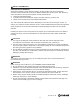
PACKAGE CONTENTS UNPACKING YOUR MITER SAW ! WARNING To avoid injury from unexpected starting or electrical shock, do not plug the power cord into a source of power during unpacking and assembly. The cord must remain unplugged whenever you are adjusting/assembling the saw. 1. Remove the miter saw from the carton. IMPORTANT: Only lift the saw by the built-in carry handles located at the top and rear of the saw. 2. Place the saw on a secure, stationary work surface. 3.
SAFETY INFORMATION PROPOSITION 65 WARNING Some dust created by power sanding, sawing, grinding, drilling and other construction activities contains chemicals known to the State of California to cause cancer, birth defects or other reproductive harm. Some examples of these chemicals are: ● Lead from lead-based paints, ● Crystalline silica from bricks and cement and other masonry products, and ● Arsenic and chromium from chemically-treated lumber.
SAFETY INFORMATION POWER TOOL SAFETY INFORMATION ! WARNING Please read and understand this entire manual before attempting to assemble, operate or install the product. These safety instructions are not meant to cover every possible condition that could occur. GENERAL SAFETY INSTRUCTIONS ● LEARN the tool’s application, limitations and possible hazards. ● KEEP GUARDS IN PLACE and in working order. ● REMOVE ADJUSTING KEYS AND WRENCHES.
● CHECK FOR DAMAGED PARTS. Check the tool for alignment of moving parts, binding of moving parts, breakage of parts or mounting and any other conditions that may affect its operation. Damaged parts should be properly repaired or replaced. ● NEVER LEAVE THE TOOL RUNNING UNATTENDED. TURN THE POWER OFF. Do not walk away from a running tool until the blade comes to a complete stop. Unplug the unit. ● DO NOT OVERREACH. Keep proper footing and balance at all times. ● MAINTAIN TOOLS WITH CARE.
● TO PREVENT severe cuts or injury, clamp all workpieces that can cause your arms, hands or fingers to move within 7-1/2 in. of the saw blade. ● PROVIDE adequate support to the sides of the saw table for long workpieces. ● NEVER use the miter saw in an area with flammable liquids or gases. ● NEVER use solvents to clean plastic parts. Solvents could possibly dissolve or otherwise damage the material. ● SHUT OFF the power before servicing or adjusting the tool.
SAFETY INFORMATION ELECTRICAL SPECIFICATIONS AND SAFETY ! CAUTION : POWER SUPPLY AND MOTOR The AC motor used in this saw is a universal, nonreversible type. See “MOTOR” in the “PRODUCT SPECIFICATIONS” section on page 2. To avoid electrical hazards, fire hazards or damage to the tool, use proper circuit protection. Your saw is wired at the factory for 120V operation. Connect to a 120V, 15A circuit and use a 15A time-delay fuse or circuit breaker.
● MOTOR is overloaded – overloading can occur if you feed too rapidly or make too many starts/stops in a short time. ● LINE VOLTAGE is more than 10% above or below the nameplate voltage rating. For heavy loads, the voltage at motor terminals must equal the voltage specified on the nameplate. ● IMPROPER or dull saw blades are used. GUIDELINES FOR EXTENSION CORDS When using an extension cord, be sure to use one heavy enough to carry the current your product will draw.
PREPARATION Before beginning assembly or operation of the product, make sure all parts are present. Compare parts with package contents list and diagram on page 3. If any part is missing or damaged, do not attempt to assemble, install or operate the product. Estimated Assembly Time: 10 minutes Tools Required for Assembly (included): Blade Wrench, 3 mm Hex Wrench Tools Required for Assembly (not included): Adjustable Wrench, 10 mm Hex Wrench, Combination Square, Phillips Screwdriver kobalttools.
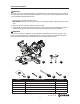
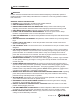
KNOW YOUR MITER SAW Switch Handle Safety Lock Power Cord Wrap Storage Motor Brush Motor Bevel Detent Pin Sliding Fence Left Extension Wing Miter Detent Override Positive Miter Stop Locking Lever Mounting Hole Carrying Handle Carrying Handle Upper Blade Guard Laser Guide Sliding Carriage Lock Knob Arbor Lock Button Hold-Down Clamp Lower Blade Guard Fence Extension Locking Lever Table Insert Stop Plate Miter Handle Table Positive Miter Stop Pencil Storage Right Extension Wing kobalttools.
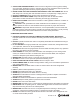
ASSEMBLY INSTRUCTIONS ! WARNING To avoid injury, do not connect this miter saw to a power source until it is completely assembled and adjusted and you have read and understood the operator’s manual. 1 INSTALLING THE MITER HANDLE (FIG. 1) ● Thread the miter handle (E) into the hole located at the front of the miter saw (A). A E UNLOCKING THE SLIDE CARRIAGE (FIG. 2) After removing the saw from the carton, loosen the slide carriage lock knob (1).
INSTALLING THE DUST BAG ASSEMBLY (FIG. 4) ● Install the dust bag assembly (C) onto the exhaust port on the miter saw (A). Fit the connecting tube of dust bag assembly and the exhaust port together. NOTE: To empty the dust bag, pull out the dust bag assembly from exhaust port. Open zipper on underside of bag and empty into waste container. 4 C A IMPORTANT: Check frequently and empty bag before it gets full. ! WARNING Do not use this saw to cut and/or sand metals.
ADJUSTMENT INSTRUCTIONS REMOVING AND INSTALLING THE TABLE INSERTS (FIG. 6) NOTE: The miter saw comes with the table inserts already installed. These instructions are for replacing or adjusting either insert side. To avoid injury: Always unplug the saw to avoid accidental ● starting. Remove all small pieces of material from the table cavity before performing any cuts. The table insert may be removed for this purpose, but always reattach the table insert prior to performing a cutting operation.
MOUNTING THE MITER SAW (FIG. 7, 8, 9) ! WARNING To avoid injury from unexpected saw movement: ● Disconnect the power cord from the outlet and lock the cutting head in the lower position using the stop latch. ● Lock the slide carriage in place by tightening the slide carriage lock knob. ● To avoid back injury, lift the saw by using the designated carrying handles located on the top of the machine. Bend with your knees, not your back. ● Never carry the miter saw by the power cord or by the switch handle.
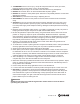
REMOVING AND INSTALLING THE BLADE ! WARNING Only use a 10 in. diameter blade. To avoid injury from an accidental start, make sure the switch is in the OFF position and the plug is not connected to the power source outlet. 10 3 1 2 REMOVING THE BLADE (FIG. 10, 11, 12) ● Unplug the saw from the outlet. ● Allow the miter saw cutting head to rise to the upright position. Raise the lower blade guard (1) to the up position. ● Loosen the cover plate screw (2) with a Phillips screwdriver.
INSTALLING THE BLADE (FIG. 10, 11, 12) Unplug the miter saw before changing/installing the blade. ● Install a 10 in. blade with a 5/8 in. arbor, making sure the rotation arrow on the blade matches the clockwise rotation arrow on the upper guard. ● Place the blade collar (7) against the blade and on the arbor. Thread the arbor bolt (6) onto the arbor (Fig. 12) in a counterclockwise direction. IMPORTANT: Make sure the flats of the blade collars are engaged with the flats on the arbor shaft.
UNLOCKING AND LOCKING THE CUTTING HEAD (FIG. 13) Unlocking the cutting head: ● To raise the cutter head from its storage/ transport position, push down slightly on the switch handle (1). ● Pull out the stop latch knob (2). ● Allow the cutting head to rise to the up position. 13 2 Locking the cutting head: When transporting or storing the miter saw, the cutting head should always be locked in the down position. ● Push the cutting head down to its lowest position.
90° Bevel Pointer Adjustment (Fig. 15): ● When the blade is exactly 90° to the table, loosen the bevel indicator screw (1) using a Phillips screwdriver. ● Adjust bevel indicator (2) to the “0” mark on the bevel scale and retighten the screw. 15 ! WARNING To avoid injury from an accidental start, make sure the switch is in the OFF position and the plug is not connected to the power source outlet. 1 2 45° Bevel Adjustment (Fig.
MITER SCALE (FIG. 17) The sliding compound miter saw scale can be easily read, showing miter angles from 0° to 50° left and right. The most common angle settings have positive stops at 0°,15°, 22.5° , 31.6°, 45° left and right and 60° right only. These positive stops position the blade at the desired angle quickly and accurately. Follow the process below for quickest and most accurate adjustments. 17 1 To Adjust Miter Angles: ● Unlock the miter table by turning the miter handle (1) counterclockwise.
SETTING CUTTING DEPTH (FIG. 19) The depth of cut can be preset for even and repetitive shallow cuts. ● Adjust the cutting head down until the teeth of the blade are at the desired depth. ● While holding the upper arm in that position, turn the stop knob (1) until it touches the stop plate (2). ● Recheck the blade depth by moving the cutting head front to back through the full motion of a typical cut along the control arm. MAXIMUM CUTTING DEPTH (FIG.
TO TURN LASER GUIDE ON (FIG. 22) ● To turn laser on, press on/off rocker switch (1) to “ON” position. ● To turn laser off, press on/off rocker switch (1) to “OFF” position. 22 ALIGNING THE LASER GUIDE (FIG. 22, 24) The laser beam must always be correctly aligned with the blade to ensure straight, even cutting. Your tool is equipped with a laser cutting guide that uses a Class IIIa laser beam. The laser beam will enable you to preview the saw blade path on the stock to be cut before starting the miter saw.
A. Check Laser Beam Alignment (Fig. 24) ● Set the saw to a 0° miter and 0° bevel setting. ● Take a board and, using a straight edge (not included), mark a 90° line on the top and front of the board. This line will serve as a “pattern line” for all laser beam alignments. Place the board on the saw table. ● Carefully lower the saw head down to align the saw blade with the pattern line.
B. Adjusting the Position of the Laser Beam (Fig. 25, 26, 27) NOTE: There are two adjustment screws on the laser guide. Use a 3 mm hex wrench to make any needed adjustments. Procedure A (Fig. 25, 26) ● Slightly turn adjustment screw (3) to adjust the vertical angle of laser beam on the front of the board.
OPERATING INSTRUCTIONS BEFORE USING THE MITER SAW ! WARNING To avoid mistakes that could cause serious, permanent injury, do not plug the tool in until the following steps are completed: ● Completely assemble and adjust the saw, following the instructions (SEE ASSEMBLY AND ADJUSTMENTS SECTIONS). ● Learn the use and function of the ON/OFF switch, upper and lower blade guards, stop latch, bevel lock handle and cover plate screws.
KEEP YOUR WORK AREA CLEAN Cluttered areas and benches invite accidents. ! WARNING To avoid burns or other fire damage, never use the miter saw near flammable liquids, vapors or gases. ● Plan ahead to protect your eyes, hands, face and ears. ● Read and understand the operator’s manual and labels affixed to the tool. Learn its application and limitations as well as the potential hazards specific to this tool.
Never cut freehand: ● Brace your workpiece firmly against the fence and table stop so it will not rock or twist during the cut. ● Make sure there is no debris between the workpiece and the table or fence. Make sure there are no gaps between the workpiece, fence and table that will let the workpiece shift after it is cut. ● Keep the cut piece free to move sideways after it is cut off. Otherwise, it could get wedged against the blade and thrown violently. ● Only the workpiece should be on the saw table.
BODY AND HAND POSITION (FIG. 28) ! WARNING Never place hands near the cutting area. Proper positioning of your body and hands when operating the miter saw will make cutting easier and safer. Keep children away. Keep all visitors at a safe distance from the miter saw. Make sure bystanders are clear of the saw and workpiece. Do not force the saw. It will do the job better and safer at its designed rate. Starting a cut: ● Place hands at least 7-1/2 in.
BASIC SAW OPERATIONS ! WARNING For your convenience, your saw has an electric brake. The brake is not a safety device. Never rely on it to replace the proper use of the guard on your saw. If the blade does not stop within 6 seconds, unplug the saw and follow the instructions in TROUBLESHOOTING. TO TURN SAW ON (FIG. 29) This miter saw is equipped with an ON/OFF trigger switch (2). With the safety lock (3) pressed, squeeze the trigger switch to turn the miter saw ON.
SLIDING FENCE (FIG. 30) ! WARNING The sliding fence must be extended when making any bevel cut. Failure to extend the sliding fence will not allow enough space for the blade to pass through which could result in serious injury. At extreme miter or bevel angles the saw blade may also contact the fence. ● Unlock the fence cam locking lever (1) by pushing it back, AWAY from the fence. ● Extend the fence (2) by sliding it out to match the degree of the bevel cut.
BEFORE LEAVING THE SAW ● Never leave tool running unattended. Turn power OFF. Wait for all moving parts to stop. ● Make workshop childproof. Lock the shop. Disconnect master switches. Store tool away from children and other unqualified users. ! WARNING To avoid injury from materials being thrown, always unplug the saw to avoid accidental starting and remove small pieces of material from the table cavity. MITER CUT (FIG.
33.9° BEVEL DETENT PIN FOR CROWN MOULDINGS (FIG. 35) ● Push the bevel detent stop pin (2) in toward the front of the machine. ● Loosen the bevel lock handle (1). ● Rotate the cutting head until the bevel detent pin stops the bevel angle at 33.9° on the bevel scale. ● Tighten the bevel lock handle before you make your cut. 35 2 1 COMPOUND CUT (FIG. 36) A compound cut is the combination of a miter and a bevel cut simultaneously. ● Extend the sliding fence as described in “ SLIDING FENCE.
TO SLIDE CUT WIDE BOARDS (FIG. 37) ● Unlock the carriage lock handle (1) and allow the cutting head assembly to move freely. ● Set both the desired bevel angle and/or the miter angle and lock into position. ● Use a hold down clamp to secure the workpiece (4). ● Grasp the switch handle (2) and pull the carriage (3) forward until the center of the saw blade is over the front of the workpiece (4). ● Engage the trigger to turn the saw on.
WORKPIECE SUPPORT AND REPETITIVE CUTTING USING THE STOP PLATE (FIG. 40, 41) NOTE: Long pieces need extension wing support. ● Lift up the lock lever (1) to unlock the extension table. Slide the extension wing to desired position and push down the lock lever to tighten. If the lock lever (1) is not tight enough, adjust the nuts (4, 5) 1/4 turn counterclockwise (Fig. 41). ● The stop plate (3) is designed for repetitive cutting. Only use one stop plate (3) at a time.
Check for interference between the wood fence and the lower blade guard. Adjust if necessary. NOTE: This auxiliary fence is used only with the saw blade in the 0° bevel position (90° to the table). The auxiliary wood fence must be removed when bevel cutting. CUTTING BASE MOULDING (FIG. 43) Base mouldings and many other mouldings can be cut on a compound miter saw. The setup of the saw depends on moulding characteristics and applications, as shown.
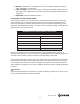
NOTE: The chart below references a compound cut for crown moulding ONLY WHEN THE ANGLE BETWEEN THE WALLS EQUALS 90°. Bevel/Miter Settings KEY BEVEL SETTING MITER SETTING TYPE OF CUT Inside corner - Left side IL 33.9° 31.6° Right 1. Position top of moulding against fence. 2. Miter table set at RIGHT 31.6°. 3. LEFT side is finished piece. 31.6° Left 1. Position bottom of moulding against fence. 2. Miter table set at LEFT 31.6°. 3. LEFT side is finished piece. 31.6° Left 1.
CROWN MOULDING CHART Compound Miter Saw Miter and Bevel Angle Settings Wall to Crown Moulding Angle 52/38° Crown Moulding 52/38° Crown Moulding 45/45° Crown Moulding Miter Setting 46.89 Bevel Setting 36.13 Angle Between Walls 124 45/45° Crown Moulding Miter Setting 18.13 Bevel Setting 21.71 Miter Setting 20.61 Bevel Setting 19.39 125 17.77 21.34 20.21 19.06 126 17.42 20.96 19.81 18.72 17.06 20.59 19.42 18.39 Angle Between Walls 67 Miter Setting 42.93 Bevel Setting 41.08 68 42.
CARE AND MAINTENANCE ! WARNING ● To avoid fire or toxic reaction, never use gasoline, naphtha acetone, lacquer thinner or similar highly volatile solvents to clean the miter saw. ● To avoid injury from unexpected starting or electrical shock, unplug the power cord before working on the saw. ● For your safety, this saw is double insulated. To avoid electrical shock, fire or injury, use only parts identical to those identified in the parts list. Reassemble exactly to avoid electrical shock.
SAWDUST Periodically, sawdust will accumulate under the worktable and base. This could cause difficulty in the movement of the worktable when setting up a miter cut. Frequently blow out or vacuum up the sawdust. If blowing sawdust, wear proper eye protection to keep debris from blowing into eyes. LUBRICATION (FIG.
TROUBLESHOOTING ! WARNING To avoid injury from accidental starting, always ensure that the switch is in the OFF position and unplug the tool before moving, replacing the blade or making adjustments. TROUBLESHOOTING - MOTOR PROBLEM PROBLEM CAUSE Brake does not 1. Motor brushes not sealed or lightly sticking. stop the blade within 6 seconds. 2. Motor brake overheated from use of defective or wrong size blade or rapid ON/OFF cycling. 3. Arbor bolt loosened. 4. Other. Motor does not 1. Blown fuse. start. 2.
REPLACEMENT PARTS LIST - SAW (PART A) I.D. 083Y 083Z 0CES 0CKS 0DVJ 0J3M 0J4E 0JZF 0JZN 0K51 0KA1 0KB7 0KB8 0KB9 0KDN 0KDR 0KE0 0KQW 0KTS 0KUW 0S2B 23NF 23NX 250Z 27PF 2BLK 2DUY 2E35 2EYT 2M0S 2MDX 2PDF 2T9B 2UYY 2VMV 2VND 2WV9 34G0 34H0 34H2 34H3 34H4 34H5 34H6 34HH 34KE 34PD 34PS 34QU 34W8 3537 35FA 35FB 35Q3 36Z2 3B3F 3CK6 3CMB 3CMC Description COMPRESSION SPRING CORD CLAMP COMPRESSION SPRING SPRING WIRE BLADE WRENCH HEX WRENCH FLAT WASHER HEX. SOC. SET SCREW ARBOR BOLT CR. RE. COUNT HD. SCREW CR.RE.
EXPLODED VIEW - SAW (PART A) kobalttools.
REPLACEMENT PARTS LIST - SAW (PART B) I.D. 0CHG 0CR8 0D8D 0HG1 0J4E 0JB0 0JE7 0JMN 0JMP 0JNR 0JUB 0K5D 0K74 0K75 0K7X 0KD7 0KDJ 0KDK 0KDR 0KDU 0KQW 0KQX 0KR3 262V 2CD7 2E7D 2EXC 2F39 2FG0 2MC0 2MC1 2MCC 2N7W 2VH6 2VN6 2VN7 2YR6 31YA 34A4 34GN 34GP 34GW 34GY 34GZ 34H1 34H7 34PJ 34PL 34Q6 34QD 34QH 34QJ 34R9 34RT 34WG 35BC 35F7 364R Description BUMPER SHAFT COLLAR COMPRESSION SPRING FLAT WASHER WAVE WASHER C-RING O-RING O-RING O-RING ROD HEX. SOC. HD. CAP BOLT CR. RE. COUNT HD. SCREW CR.-RE. TRUSS HD.
EXPLODED VIEW - SAW (PART B) kobalttools.
REPLACEMENT PARTS LIST - SAW (PART C) I.D. 082J 0CPD 0J4M 0J69 0J6A 0J7G 0JB0 0JBG 0JPF 0JX9 0K2N 0K55 0K6X 0KD6 0KDG 0KDR 0KDS 0KDV 0KMS 0KQW 0KQX 0KR0 0KR2 0KR4 22QE 2BEL 2BLG 2BQA 2CD2 2D9W 2MBK 2MBL 2MC8 2VZ1 2WRN 31XE 349F 349G 34AA 34GM 34GQ 34GR 34GS 34NJ 34NK 34Q5 34Q7 34W7 3527 35C1 35F6 35F8 35F9 35FC 35FD 35FE Description CUSHION CENTER BOLT FLAT WASHER FLAT WASHER FLAT WASHER FLAT WASHER WAVE WASHER DISC SPRING WASHER HEX. HD. BOLT HEX. SOC. SET SCREW HEX SOC. HD. CAP SCREW CR. RE. COUNT HD.
EXPLODED VIEW - SAW (PART C) kobalttools.
PARTS LIST - MOTOR I.D. Description Size Q’ty 3492 MOTOR REAR COVER 1 0HX9 NEEDLE BEARING 1 0JBA WAVE WASHER 1 0JCD SPRING PIN 1 0JE0 C-RING 1 0JEB C-RING 1 0JEE C-RING 1 0JG7 PARALLEL KEY 1 0JX2 HEX. SOC SET SCREW M5*0.8-6 2 0K43 CR.RE. PAN HD. SCREW & WASHER M5*0.8-16 2 0K44 CR.RE. PAN HD. SCREW & WASHER M5*0.8-12 1 0KAA CR.RE. PAN HD.
EXPLODED VIEW - MOTOR kobalttools.
PAGE BLANK INTENTIONALLY kobalttools.
WARRANTY The manufacturer will offer replacement parts for this product which under normal usage have proven to be defective in their manufacture or workmanship for a period of THREE (3) years from the date of initial retail purchase. This warranty is valid only to the original purchaser. This warranty is not transferable and does not cover any parts that have been subjected to misuse, abuse, alteration, overload, accident or normal wear of moving parts.