KOBE Brand Range Hood Model No.
- READ AND SAVE THESE INSTRUCTIONS - CONTENTS IMPORTANT SAFETY INSTRUCTIONS.........................ERROR! BOOKMARK NOT DEFINED. COMPONENTS OF PACKAGE ................................................................................................. 3 INSTALLATION ......................................................................................................................... 4 UNDER THE CABINET INSTALLATION .................................................................................
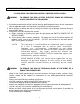
IMPORTANT SAFETY INSTRUCTIONS - PLEASE READ THIS SECTION CAREFULLY BEFORE INSTALLATION WARNING: TO REDUCE THE RISK OF FIRE, ELECTRIC SHOCK OR PERSONAL INJURY, OBSERVE THE FOLLOWING: 1) Installation and electrical wiring must be done by qualified professionals and in accordance with all applicable codes and standards, including fire-rated construction. 2) When cutting or drilling into wall or ceiling, be careful not to damage electrical wiring or other hidden utilities.
What to Do In The Event Of a Range Top Grease Fire • • • • SMOTHER FLAMES with a close fitting lid, cookie sheet, or metal tray, and then turn off the burner. KEEP FLAMMABLE OR COMBUSTIBLE MATERIAL AWAY FROM FLAMES. If the flames do not go out immediately, EVACUATE THE AREA AND CALL THE FIRE DEPARTMENT or 911. NEVER PICK UP A BURNING PAN – You May Get Burned. DO NOT USE WATER, including wet dishcloths or towels – a violent steam blast will result.
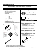
COMPONENTS OF PACKAGE (Must keep all material for returns or refunds) RANGE HOOD BOX KOBE Range Hood – 1 Warranty Registration Card –1 Instructions Manual – 1 Baffle Filter - 2 (30”, 36”, 42”) - 3 (48”) Stainless Steel Spacer - 0 (30”) - 1 (36”) - 2 (42”, 48”) Oil Tunnel – 1 Ducting Transition – 1 Screw Package for Transition – 1 Hood-Mounting Bracket-2 Screw Package for Hood-Mounting Bracket –1 3/16" X 3/8" (8 pc) DUCT COVER KIT (Sold Separately) Option Of: Model No.
INSTALLATION PLEASE READ ENTIRE INSTRUCTION BEFORE PROCEEDING Calculation before Installation To calculate installation, please refer to Table 1. (All calculation in inches.
SAFETY WARNING HOOD MAY HAVE VERY SHARP EDGES; PLEASE WEAR PROTECTIVE GLOVES IF IT IS NECESSARY TO REMOVE ANY PARTS FOR INSTALLING, CLEANING OR SERVICING. NOTE: BE CAREFUL WHEN USING ELECTRICAL SCREWDRIVER, DAMAGE TO THE HOOD MAY OCCUR. Installation Table of Contents UNDER THE CABINET INSTALLATION................................................................................6 Preparation Before Installation ................................................................................................
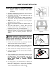
UNDER THE CABINET INSTALLATION Preparation Before Installation NOTE: TO AVOID DAMAGE TO YOUR HOOD, PREVENT DEBRIS FROM ENTERING THE VENT OPENING. • • • • • • • Decide the location of the venting pipe from the hood to the outside. Refer to Figure 1. A straight, short vent run will allow the hood to perform more efficiently. Try to avoid as many transitions, elbows, and long runs as possible. This may reduce the performance of the hood.
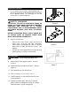
Ductwork Installation 7. Use 8” aluminum or steel pipe (follow building codes in your area) to connect the ducting transition on the hood to the ductwork above. Use duct tape to seal and secure joints as shown in Figure 5. Wiring to Power Supply S AF E T Y W AR N I N G TO PREVENT THE RISK OF ELECTRICAL SHOCK OR INJURY, ALL RANGE HOODS SHOULD BE PROPERLY GROUNDED AND INSTALLED BY A TRAINED PROFESSIONAL WHO IS KNOWLEDGEABLE ABOUT APPLICABLE NATIONAL AND LOCAL ELECTRICAL CODES.
15. Install heating lamps (not provided), 120 Volts 175 Watts max. each. 16. Turn power ON in control panel. Check all lights and fan operation. 17.
STAND ALONE INSTALLATION ***Follow these installations only if installing with an optional duct cover: Preparation Before Installation NOTE: TO AVOID DAMAGE TO YOUR HOOD, PREVENT DEBRIS FROM ENTERING THE VENT OPENING. • • • • • • Decide the location of the venting pipe from the hood to the outside. Refer to Figure 9. A straight, short vent run will allow the hood to perform more efficiently. Try to avoid as many transitions, elbows, and long run as possible. This may reduce the performance of the hood.
2. 3. Align hood-mounting bracket to the two screws on the wall and hook hood into place. Tighten screws to secure hood to the wall. WALL For safety purpose, extra knockout holes on the back of the hood are provided for a more secure installation. Knock out as many holes as needed and secure with screws (not provided) from the inside of hood. CAUTION: MAKE SURE HOOD IS SECURE BEFORE RELEASING.
Duct Cover Installation 5. Use 8” aluminum or steel pipe (follow building codes in your area) to connect the ducting transition on the hood to the ductwork above. Use duct tape to seal and secure joints as shown in Figure 15. Slide the duct cover onto the hood. 6. Use 3/16” x 3/8” screws (provided) to attach duct cover to hood. Figure 15 Final Assembly CAUTION: Install heating lamps last. 7. Drop Oil Tunnel into support structure. Refer to Figure 7. 8. Angle baffle filter toward back of hood .
OPERATING INSTRUCTIONS This KOBE hood is equipped with touch-sensor screen and features 3 minute delay shutoff, powerful centrifugal squirrel cage with baffle filters, bright 12-volt 20-watt halogen lights and heating lamp capability (heating lamps not included). The touch-sensor screen has Heat Lamp Control, Light Control, Speed Control (QuietMode™, Low, Medium and High), and Power Control. Refer to Figure 18.
Turn Off After 3 Minute Delay Gently touch the symbol under the Power Control sign once, the symbol flashes and after 3 minutes, the hood will turn off leaving only the sign lit. Speed Control: • There are four speeds: QuietMode™, Low, Medium, and High. To activate the speed, touch the control under the speed sign. For example, if turning on hood at low speed, gently touch the symbol under the sign.
MAINTENANCE SAFETY WARNING NEVER PUT YOUR HAND INTO AREA HOUSING THE FAN WHILE THE FAN IS OPERATING. For optimal operation, clean range hood and all baffle/spacer/filter/oil tunnel/oil container regularly. To Clean Hood Surface CAUTION: NEVER USE ABRASIVE CLEANERS, PADS, OR CLOTHS. *** Regular care will help preserve the appearance of the hood. 1. Use only mild soap or detergent solutions. Dry surfaces using soft cloth. 2.
To Replace Light Bulb CAUTION: HALOGEN LIGHT UNIT MAY BE HOT! WAIT UNTIL UNIT IS COOL. 1. Make sure all controls are off, and range hood is unplugged. 2. Place a flat-head screwdriver between light cover and housing to remove cover . 3. Gently pull defective bulb straight out and discard. Light bulbs should be 12V 20W maximum. 4. Wear a cotton glove or use a cloth to handle the replacement bulb (do not handle with bare fingers as this may shorten the life of the bulb).
SPECIFICATIONS MODEL / SIZE CH0130SQB / 30” CH0136SQB / 36” CH0142SQB / 42” CH0148SQB / 48” DESIGN 18-Gauge Seamless Commercial Stainless Steel CONSUMPTION / AMPERE 702W / 5.85A – 30”, 36” 722W / 6.02A – 42”, 48” VOLTAGE 120V 60Hz NUMBER OF MOTORS 1 FAN TYPE: CENTRIFUGAL Squirrel Cage EXHAUST Top Transition Rectangular to 8” Round x 1 CONTROLS Touch Sensor Screen HALOGEN LIGHTS 30” / 36” - 12V20W x 2 42” / 48” - 12V20W x 3 HEATING LAMPS 120V 175W Max.
MEASUREMENTS & DIAGRAMS *** Inch measurements converted from millimeter. Inch measurements are estimated. - FOR UNDER THE CABI NET MODEL NO: CH0130SQB CH0136SQB CH0142SQB CH0148SQB 11/2 " (12 ) 1- 1/4 " 6 (32 ) 12" 1 (30 5) 1 4- 2) " (3 4 / -1 2- 32) ( " /4 -1 1/8 " (54 ) 06) 3 ( 12" 1/2 " (1 66) 2) "(3 4 / -1 8" ( 203 ) 1/2 " 3 - 1/8" (79.
- FOR UNDER THE CABI NET – (Cont.
- FOR STAND ALONE (WITH OPTIONAL DUCT COVER) – CH0130SQB CH0136SQB CH0142SQB CH0148SQB 7- 5) 90. 1 ( " 1/2 1- 1- 6 1/4 " (3 2) 65) " (1 2 / -1 1 2 0) " (7 4 / -3 5) 52. 1 ( 6" 2) " (3 4 / -1 2- 4- 1/2 " (1 14) ) 1 18 - 7/8" (480) 18" (457) 19 - 1/3" (491) 12" (30 1 5) 8" ( 203 ) 1/8 " (5 4) 06) 3 ( 12" 1" ( 6 - 1 /2" 25) (16 6) 32) ( " 1/4 7/8 " (4 8) 3 - 1/8" (79.
3 - 1/8" (79.5) 12 " (3 05 ) 18" (457) 30" (762) (12") (305) - FOR STAND ALONE (WITH OPTIONAL DUCT COVER) – (Cont.
4" (102) 1/3" (8.5) 1/2" (13) 1" (25.4) 1 - 3/8" (35) 1/4" (6.5) 3/16" (5) 11/16" (17.5) Hood-Mounting Bracket 6" (152) 7 - 1/2" (190.
PARTS LIST MODEL NO: CH0130SQB CH0136SQB CH0142SQB CH0148SQB BODY COMPONENTS NO.
3 2 1 4 5 23 22 6 7 9 21 20 8 18 3 16 19 10 11 15 14 12 17A 17B 13 17 Optional Duct Cover (Sold Separately) 24 3 23
Blower Assembly NO. 4.1 4.2 4.3 4.4 4.5 4.6 4.7 4.8 DESCRIPTION Screws (3/16” x 3/8”) Air Flow Grill Left Locknut Left Squirrel Cage Motor Right Squirrel Cage Right Locknut Air Chamber MODEL / SIZE 24 PART NO. CH101-4.1 CH101-4.2 CH101-4.3 CH101-4.4 CH101-4.5 CH101-4.6 CH101-4.7 CH101-4.
Electrical Assembly NO. 21.1 21.2 21.3 21.4 21.5 21.6 21.7 21.8 21.9 21.10 21.11 21.12 21.13 DESCRIPTION Bolt Electrical Box Screws (3/16” x 3/8”) Power Board Electrical Box Cover Setup Board Screws (3/16” x 3/8”) Capacitor Transformer Bolt Gasket Screw Cap Rubber Gasket Screws (3/16” x 3/8”) MODEL / SIZE PART NO. CH101-21.1 CH101-21.2 CH101-21.3 CH101-21.4 CH101-21.5 CH101-21.6 CH101-21.7 CH101-21.8 CH101-21.9 CH101-21.10 CH101-21.11 CH101-21.12 CH101-21.13 21.1 21.2 21.11 21.10 21.12 21.13 21.
Switch Assembly NO. 20.1 20.2 20.3 20.4 20.5 20.6 DESCRIPTION Screen Support Touch Screen Switch Box Switch Board Switch Box Cover Screws (1/8” x 1/2”) MODEL / SIZE PART NO. CH101-20.1 CH101-20.2 CH101-20.3 CH101-20.4 CH101-20.5 CH101-20.6 20.1 20.6 20.2 20.3 20.4 20.
CIRCUIT DIAGRAM MODEL NO.
MODEL NO.
DISCLAIMER 1. CAREFULLY INSPECT ALL ITEMS FOR DAMAGES BEFORE ACCEPTING DELIVERY. NOTE ANY DAMAGES ON THE FREIGHT BILL OR EXPRESS RECEIPT. REQUEST NAME AND SIGNATURE OF THE CARRIER’S AGENT AND KEEP COPY TO SUPPORT YOUR CLAIM. Upon acceptance of items, owner assumes responsibility for its safe arrival. Damages should be reported to carrier and a claim filed. Failure to do this could result in the carrier refusing to honor your claim. The carrier will furnish you with necessary forms for filing a claim.
WARRANTY WARRANTY CERTIFICATE KOBE Range Hoods, Inc. warrants all products manufactured or supplied by it to be free from defects in workmanship and materials. Its obligations pursuant to this warranty are limited to a period of two years from the date of purchase and to the repair or replacement at its option and subject to the terms and conditions stated below, of any component part, which its examination shall disclose to be so defective.
h) for damage by or resulting from attempted repairs conducted by anyone other than our Authorized Service Agent.
PRODUCT REGISTRATION Register Your Product! Any covered failure occurring within two years of original purchase arising from defective workmanship or material in manufacture will be repaired or at our option the unit will be replaced free of charge by an authorized KOBE Range Hoods Agent or KOBE Range Hoods as applicable. Keep proof of purchase (original invoice) handy for inspection.
KOBE Range Hoods 10505 Valley Blvd Suite # 302 El Monte, CA 91731 USA http://www.KOBERangeHoods.com This KOBE hood is made for use in the USA and CANADA only. We do not recommend using this hood overseas as the power supply may not be compatible and may violate the electrical code of that country. Using a KOBE hood overseas is at your own risk and will void your warranty. V.