KOBE Brand Range Hood Model No.
- READ AND SAVE THESE INSTRUCTIONS - CONTENTS Important Safety Instructions………………………………………………………………. Components of Package…………………………………………………………………… Installation…………………………………………………………………………………… Operating Instructions.…………………………………...………………………………… Maintenance…………………………………………………………………………………. Specifications…………………………………………………….……..…………………… Measurements & Diagrams…………………………………………………………...…… Parts List…………………………………………………………………..…………………. Circuit Diagram………………………………………………………………...…………….
IMPORTANT SAFETY INSTRUCTIONS - PLEASE READ THIS SECTION CAREFULLY BEFORE INSTALLATION WARNING – TO REDUCE THE RISK OF FIRE, ELECTRIC SHOCK OR PERSONAL INJURY, OBSERVE THE FOLLOWING: 1) Installation and electrical wiring must be done by qualified professionals and in accordance with all applicable codes and standards, including fire-rated construction. 2) When cutting or drilling into wall or ceiling, be careful not to damage electrical wiring or other hidden utilities.
What to Do In The Event Of a Range Top Grease Fire - - SMOTHER FLAMES with a close fitting lid, cookie sheet, or metal tray, and then turn off the burner. KEEP FLAMMABLE OR COMBUSTIBLE MATERIAL AWAY FROM FLAMES. If the flames do not go out immediately, EVACUATE THE AREA AND CALL THE FIRE DEPARTMENT or 911. NEVER PICK UP A BURNING PAN – You may get burned. DO NOT USE WATER, including wet dishcloths or towels – a violent steam blast will result.
COMPONENTS OF PACKAGE (Must keep all material for returns or refunds) Range Hood Box Duct Cover Box (Sold Separately) {A} KOBE Range Hood {B} Warranty Registration Card {C} Instructions Manual {D} Vent Cover (Top) {E} Oil Containers (Round) {F} Oil Containers (Oval) {G} KOBE Duct Cover (Model No.
INSTALLATION PLEASE READ ENTIRE INSTRUCTIONS BEFORE PROCEEDING Calculation before Installation Calculate the length of the installation, before installing the hood. (All calculation is measure in inches.
SAFETY WARNING HOOD MAY HAVE VERY SHARP EDGES; PLEASE WEAR PROTECTIVE GLOVES IF IT IS NECESSARY TO REMOVE ANY PARTS FOR INSTALLING, CLEANING OR SERVICING. NOTE: BE CAREFUL WHEN USING ELECTRICAL SCREWDRIVER, DAMAGE TO THE HOOD MAY OCCUR. Installation Contents UNDER THE CABINET Top Vent………………………………………………………………………………… Rear Vent……………………………………………………………………………….. 6 8 STAND ALONE Top Vent………………………………………………………………………………… Rear Vent………………………………………………………………………………..
UNDER THE CABINET INSTALLATION – TOP VENT Preparation before Installation NOTE: TO AVOID DAMAGE TO YOUR HOOD, PREVENT DEBRIS FROM ENTERING THE VENT OPENING. - Decide the location of the venting pipe from the hood to the outside. Refer to Figure 1. - A straight, short venting run will allow the hood to perform more efficiently. - Try to avoid as many transitions, elbows, and long run as possible. This may reduce the performance of the hood.
2. 3. Unscrew the six screws on the bottom casing. Remove the bottom casing If necessary, arrange the electrical wires to run through the 1” diameter hole on the top or the rear of the hood. Refer to Figure 5. Using references on Table 1 and measurements on page 21 center the hood in place beneath the cabinet and flush with the front of the cabinet. 1” Diameter Hole Figure 4 4. 5. Figure 5 Draw electrical wires through cabinet access opening.
UNDER THE CABINET INSTALLATION – REAR VENT Preparation before installation NOTE: TO AVOID DAMAGE TO YOUR HOOD, PREVENT DEBRIS FROM ENTERING THE VENT OPENING. - Decide the location of the venting pipe from the hood to the outside. Refer to Figure 6. - A straight, short venting run will allow the hood to perform more efficiently. - Try to avoid as many transitions, elbows, and long run as possible. This may reduce the performance of the hood.
1. 2. Puncture the knockout holes on the hood as shown in Figure 10. Unscrew and remove the multi duct exhaust. Replace with {D} vent cover (top) on page 3. Refer to Figure 11. Figure 10 3. 4. 5. Figure 11 Unscrew the six screws on the bottom casing. Remove the bottom casing. If necessary, arrange the electrical wires to run through the 1” diameter hole on the top or the rear of the hood. Refer to Figure 12.
STAND ALONE INSTALLATION – TOP VENT ***This installation only applied with the purchase of a duct cover (Model No. CH1120DC). Preparation before Installation NOTE: TO AVOID DAMAGE TO YOUR HOOD, PREVENT DEBRIS FROM ENTERING THE VENT OPENING. - Decide the location of the venting pipe from the hood to the outside. Refer to Figure 13. - A straight, short venting run will allow the hood to perform more efficiently. - Try to avoid as many transitions, elbows, and long run as possible.
- If necessary, attach two rubber stands (provided) with two (4x8 mm) screws (provided) to the back of the hood. - Attach the hood-mounting bracket to the back of the hood with nine (3/16” x 3/8”) screws (provided) as shown in Figure 16. Hood Installation CAUTION: If required to move the cooking range to install the hood, turn off the power on an electric range at the main electrical box. SHUT OFF THE GAS BEFORE MOVING A GAS RANGE. 1.
Figure 18 7. Figure 19 Adjust the height of the inner duct cover to the duct cover-mounting bracket. Secure the inner duct cover with two (4x8 mm) screws (provided) as shown in Figure 20. Attach Together Figure 20 8. 9. Fasten outer duct cover to multi vent exhaust on the hood with four (4x8 mm) screws (provided). Continued at “Install Accessories” on page 16.
STAND ALONE INSTALLATION – REAR VENT ***This installation only applied with the purchase of a duct cover (Model No. CH1120DC). Preparation before Installation NOTE: TO AVOID DAMAGE TO YOUR HOOD, PREVENT DEBRIS FROM ENTERING THE VENT OPENING. - Decide the location of the venting pipe from the hood to the outside. Refer to Figure 21. - A straight, short venting run will allow the hood to perform more efficiently. - Try to avoid as many transitions, elbows, and long run as possible.
- If necessary, attach two rubber stands (provided) with two (4x8 mm) screws (provided) to the back of the hood. - Attach the hood-mounting bracket to the back of the hood with nine (3/16” x 3/8”) screws (provided) as shown in Figure 25. Hood Installation CAUTION: If required to move the cooking range to install the hood, turn OFF the power on an electric range at the main electrical box. SHUT OFF THE GAS BEFORE MOVING A GAS RANGE. 1.
Figure 27 7. Figure 28 Adjust the height of the inner duct cover to the duct cover-mounting bracket. Secure the inner duct cover with two (4x8 mm) screws (provided) as shown in Figure 29. Attach Together Figure 29 8. 9. Fasten outer duct cover to multi vent exhaust on the hood with four (4x8 mm) screws (provided). Continued at “Install Accessories” on page 16.
Wiring to Power Supply SAFETY WARNING RISK OF ELECTRICAL SHOCK. THIS RANGE HOOD MUST BE PROPERLY GROUNDED. MAKE SURE THIS IS DONE BY SPECIALIZED ELECTRICIAN IN ACCORDANCE WITH ALL APPLICABLE NATIONAL AND LOCAL ELECTRICAL CODES. BEFORE CONNECTING WIRES, SWITCH POWER OFF AT SERVICE PANEL AND LOCK SERVICE PANEL TO PREVENT POWER FROM BEING SWITCHED ON ACCIDENTALLY. 1. Connect the electrical wires. - If necessary to hide the electrical wire connections, push wires back into the wiring box.
OPERATING INSTRUCTIONS This KOBE hood is equipped with four electronic controls with a 10-second standby startup & 30-second delay shutoff, two powerful centrifugal turbine impellers with safety screens, two bright 12-volt 20-watt halogen lights, and four oil containers. The four electronic controls are Light Control, Speed Control A (cycles through Low, Medium, High, QuietMode), Speed Control B (cycles through Low, QuietMode, High, Medium) and the Power Control (On/Off). Refer to Figure 32.
MAINTENANCE CAUTION: NEVER PUT YOUR HAND INTO THE AREA HOUSING THE FAN WHILE THE FAN IS OPERATING. For the optimal level of operation, clean the range hood surface, safety screens, and oil containers regularly. To Clean Hood Surface CAUTION: NEVER USE ABRASIVE CLEANERS, PADS, OR CLOTHS. *** Regular care will help preserve its fine appearance. 1) Use only mild soap or detergent solutions. Dry surfaces using soft cloth.
To Replace Light Bulb CAUTION: HALOGEN LIGHT UNIT MAY BE HOT! WAIT UNTIL UNIT IS COOL. 1) Make sure all control switches are off, and range hood is unplugged. 2) Use a flat head screwdriver to pop out the protective covering as shown in Figure 33. 3) Gently pull out the defective light bulb and discard. Light bulbs should be 12V 20W maximum. Refer to Figure 34. Push bulb securely into light socket. 4) Replace protective cover. 5) Plug in range hood.
SPECIFICATIONS MODEL / SIZE CH2230SQ / 30” CH2236SQ / 36" COLOR # 304 Commercial Grade Stainless Steel VOLTAGE 120V 60Hz NUMBER OF MOTORS DESIGN 2 18-Gauge Seamless / Satin Finish FAN TYPE Twin Turbine Impeller EXHAUST Top – 6” Round 7” Round 3-1/4” x 10” Rectangular Rear – 3-1/4” x 10” Rectangular CONTROLS Electronic Control (4 Buttons) – 10-Second Standby Startup 30-Second Delay Shutoff HALOGEN LIGHTS 12V 20W x 2 HOOD DIMENSION (W x D x H) (CH2230SQ) 29-3/4” x 22” x 5-7/8” (CH2236SQ) 35-
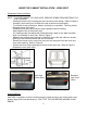
MEASUREMENTS & DIAGRAMS ***All inch measurements are converted from millimeters. Inch measurements are estimated. ***All measurements in ( ) are millimeters.
***Hood-Mounting Bracket ***Duct Cover-Mounting Bracket 22
PARTS LIST MODEL NO.: CH2230SQ CH2236SQ NO.
MODEL NO.
CIRCUIT DIAGRAM MODEL NO.
DISCLAIMER 1. CAREFULLY INSPECT ALL ITEMS FOR DAMAGES BEFORE ACCEPTING DELIVERY. NOTE ANY DAMAGES ON THE FREIGHT BILL OR EXPRESS RECEIPT. REQUEST NAME AND SIGNATURE OF THE CARRIER’S AGENT AND KEEP COPY TO SUPPORT YOUR CLAIM. Upon acceptance of items, owner assumes responsibility for its safe arrival. Damages should be reported to carrier and a claim filed. Failure to do this could result in the carrier refusing to honor your claim. The carrier will furnish you with necessary forms for filing a claim.
WARRANTY WARRANTY CERTIFICATE KOBE Range Hoods, Inc. warrants all products manufactured or supplied by it to be free from defects in workmanship and materials. Its obligations pursuant to this warranty are limited to a period of two years from the date of purchase and to the repair or replacement at its option and subject to the terms and conditions stated below, of any component part, which its examination shall disclose to be so defective.
3) The purchaser shall be responsible for any expenses involved in making the range hood readily accessible for servicing and where the range hood is installed outside the main sales territory of the retailer or service territory of the nearest approved KOBE Range Hoods Agent as applicable, for any traveling expenses and any costs of transporting the range hood or parts thereof to and from the dealer or Service Agent 4) The purchaser must produce proof of purchase together with this warranty certificate whe
PRODUCT REGISTRATION Register Your Product! Any covered failure occurring within two years of original purchase arising from defective workmanship or material in manufacture will be repaired or at our option the unit will be replaced free of charge by an authorized KOBE Range Hoods Agent or KOBE Range Hoods as applicable. Keep proof of purchase (original invoice) handy for inspection.