KOBE Brand Range Hood Model No.
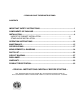
- READ AND SAVE THESE INSTRUCTIONS - CONTENTS IMPORTANT SAFETY INSTRUCTIONS .........................................................................1 COMPONENTS OF PACKAGE .......................................................................................3 INSTALLATION................................................................................................................4 UNDER THE CABINET INSTALLATION ............................................................ 6 STAND ALONE INSTALLATION ...
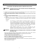
IMPORTANT SAFETY INSTRUCTIONS - PLEASE READ THIS SECTION CAREFULLY BEFORE INSTALLATION - WARNING: TO REDUCE THE RISK OF FIRE, ELECTRIC SHOCK OR PERSONAL INJURY, OBSERVE THE FOLLOWING: 1) Installation and electrical wiring must be done by qualified professionals and in accordance with all applicable codes and standards, including fire-rated construction. 2) When cutting or drilling into wall or ceiling, be careful not to damage electrical wiring or other hidden utilities.
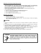
What to Do In The Event Of a Range Top Grease Fire • • • • SMOTHER FLAMES with a close fitting lid, cookie sheet, or metal tray, and then turn off the burner. KEEP FLAMMABLE OR COMBUSTIBLE MATERIAL AWAY FROM FLAMES. If the flames do not go out immediately, EVACUATE THE AREA AND CALL THE FIRE DEPARTMENT or 911. NEVER PICK UP A BURNING PAN – You May Get Burned. DO NOT USE WATER, including wet dishcloths or towels – a violent steam blast will result.
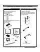
COMPONENTS OF PACKAGE (Must keep all material for returns or refunds) Range Hood Box Duct Cover Box (Sold Separately) {A} KOBE Range Hood {B} Warranty Registration Card {C} Instruction Manual {D} Baffle Filter -- 2 (30”, 36”, 42”) -- 3 (48”) {E} Stainless Steel Spacer -- 0 (30”) -- 1 (36”) -- 3 (42”) -- 2 (48”) {F} Hood-Mounting Bracket w/ Screws Set {G} Rubber Stand {H} Oil Tunnel {I} KOBE Duct Cover (Model No.
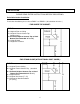
INSTALLATION PLEASE READ ENTIRE INSTRUCTIONS BEFORE PROCEEDING Calculation before Installation To calculate installation, please refer to TABLE 1 or TABLE 2. (All calculation in inches.
SAFETY WARNING HOOD MAY HAVE VERY SHARP EDGES; PLEASE WEAR PROTECTIVE GLOVES IF IT IS NECESSARY TO REMOVE ANY PARTS FOR INSTALLING, CLEANING OR SERVICING. NOTE: BE CAREFUL WHEN USING ELECTRICAL SCREWDRIVER, DAMAGE TO THE HOOD MAY OCCUR. Installation Contents UNDER THE CABINET INSTALLATION ........................................................................6 PREPARATION BEFORE INSTALLATION ............................................................................. 6 HOOD INSTALLATION ................
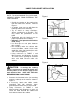
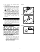
UNDER THE CABINET INSTALLATION Preparation before Installation NOTE: TO AVOID DAMAGE TO YOUR HOOD, PREVENT DEBRIS FROM ENTERING THE VENT OPENING. • • • • • • • • Figure 1 Decide the location of the venting pipe from the hood to the outside. Refer to Figure 1. A straight, short vent run will allow the hood to perform more efficiently. Try to avoid as many transitions, elbows, and long run as possible. This may reduce the performance of the hood.
4. Draw electrical wires through cabinet access opening. 5. From inside of the hood, place screw (not provided) into the exact center of each knockout hole and secure to cabinet bottom. Once all mounting screws are in place, finish tightening screws until secure. Figure 4 CAUTION: MAKE SURE THE HOOD IS SECURE BEFORE RELEASING. 6. For safety purpose, pre-drilled mounting holes are provided through the back of the hood.
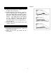
Figure 7 Accessories 9. Drop oil tunnel into recess support near rear of hood. Refer to Figure 6. 10. Install baffle filters and stainless spacer(s). Refer to Measurements and Diagrams on page 22 for baffle filter and stainless spacer placement. Angle baffle filter toward back of hood . Push baffle filter up until almost level . Slide forward into recess behind the front of hood . Lower baffle filter . Slide back until it fits into resting position . Refer to Figure 7. 11.
STAND ALONE INSTALLATION *** This installation only applies if installing with the CH1120DC duct cover. Figure 8 Preparation before Installation NOTE: TO AVOID DAMAGE TO YOUR HOOD, PREVENT DEBRIS FROM ENTERING THE VENT OPENING. • • • • • • • • Decide the location of the venting pipe from the hood to the outside. (Figure 8) A straight, short vent run will allow the hood to perform more efficiently. Try to avoid as many transitions, elbows, and long run as possible.
1. Using references in TABLE 1 and Measurements and Diagrams on pages 19-21, mark the leveling point of the hood. Position two mounting screws (not provided) on the wall, leaving 1/8” space away from the wall. 2. Puncture the knockout wire access hole at the back of the hood and draw the electrical wires through as shown in Figure 12. 3. Align hood-mounting bracket to the screws on the wall and hook hood into place as shown in Figure 13. Tighten screws to secure hood to the wall. 4.
Duct Co ver Installation Figure 15 6. Mark the position of the inner duct covermounting bracket {J} (provided). Use reference E from TABLE 2 and Measurements and Diagrams on page 20-21. Attach and secure inner duct cover-mounting bracket {J} with two screws (not provided) to the wall. Refer to Figure 15. NOTE: Inner duct cover will be attached to the mounting bracket. 7. Use 7” round steel pipe (follow building codes in your area) to connect the round exhaust on the hood to the ductwork above.
Figure 19 Final Assembl y 14. Turn power ON in control panel. Check all light and fan operation. 15. Make sure to leave this manual for the homeowner.
OPERATION INSTRUCTIONS This KOBE hood is equipped with six electronic controls, two powerful centrifugal squirrel cages with stainless steel oil tunnel, stainless steel baffle filters and spacer(s), and bright 12volt 20-watt halogen lights (2 for 30” & 36” and 3 for 42” & 48”). The six electronic buttons control the Light, Speed (QuietMode™, Low, Medium & High) and Power (On/Off). The Power Control offers a 10-second delay startup, 3-minute delay shutoff or immediate shutoff.
Figure 21 Turning Fan OFF: The 3-Minute Delay function will only turn off fans. The light settings will not be affected by the delay function. 3-Minute Delay - Press Power Control (On/Off) button once, the LED light for the active speed will flash and fans will shut off after 3 minutes. - During this 3-minute delay, changing speeds will not affect the 3 minute countdown. Immediate Shutoff - Press Power Control (On/Off) button twice, the fans will be shut off immediately.
MAINTENANCE SAFETY WARNING NEVER PUT YOUR HAND INTO AREA HOUSING THE FAN WHILE THE FAN IS OPERATING. For optimal operation, clean range hood and all baffle/spacer/filter/oil tunnel/oil container regularly. To Clean Hood Surface CAUTION: NEVER USE ABRASIVE CLEANERS, PADS, OR CLOTHS. *** Regular care will help preserve the appearance of the hood. 1. Use only mild soap or detergent solutions. Dry surfaces using soft cloth. 2.
To Replace Light Bulb CAUTION: HALOGEN LIGHT UNIT MAY BE HOT! WAIT UNTIL UNIT IS COOL. 1. Make sure all controls are off, and range hood is unplugged. 2. Place a flat-head screwdriver between light cover and housing to remove cover . 3. Gently pull defective bulb straight out and discard. Light bulbs should be 12V 20W maximum. 4. Wear a cotton glove or use a cloth to handle the replacement bulb (do not handle with bare fingers as this may shorten the life of the bulb).
SPECIFICATIONS MODEL / SIZE CH7630SQB / 30” CH7636SQB / 36" CH7642SQB / 42” CH7648SQB / 48” COLOR #304 Commercial Grade Stainless Steel CONSUMPTION / AMPERE CH7630SQB – 300W / 3A CH7636SQB – 300W / 3A CH7642SQB – 300W / 3A CH7648SQB – 300W / 3A VOLTAGE 120V 60Hz NUMBER OF MOTORS 2 DESIGN Seamless / Satin Finish MOTOR TYPE Vertical Squirrel Cage EXHAUST Top 7” Round CONTROLS Six Electronic Buttons HALOGEN LIGHTS CH7630SQB - 12V 20W x 2 CH7636SQB - 12V 20W x 2 CH7642SQB - 12V 20W x 3 CH7648
MEASUREMENTS & DIAGRAMS All ( ) are in millimeter. All inch measurements are converted from millimeters. Inch measurements are estimated.
All ( ) are in millimeter. All inch measurements are converted from millimeters. Inch measurements are estimated.
4" (10 2 2" (51) Rear Knockout Holes ) 3" (75 ) 3 " ( 75 ) 12 18 " (3 24 " (45 04) fo "( 6 r 30 " (7 608) ) for 30" 36 for 60 ) fo 42 " " r4 8" 3" ( 75 20 ) 3 " (7 5)
1/2" (13) 11/16" (18) Hood-Mounting Bracket 4-3/4" (120) 9 " (2 2 8 ) 1-3/8" (35) 8 -5 /8 " (2 2 0) 1-3/8" (36) 9 " (22 8 ) 1 0 -5 /8" (2 7 0) DUCT COVER-MOUNTING BRACKET Inner Duct Cover-Mounting Bracket 8) 29 ( " 3/4 /8 8-5 8) ( 29 ) " 0 4 -3/ " (22 11 /8 8- 5 .5) 9) 21 ( " 23- 1 1/ 4" (5 /8" ( 80 7 ) ) 21 7/8" (22) 11 (32 1/8" (4.5) 1-3/16" (30) 1 -1 /4" Outer Duct Cover-Mounting Bracket 1/8" ( 3.
BAFFLE FILTER & STAINLESS STEEL SPACERS 30″ H00D 42″ H00D 36″ H00D 48″ H00D 22
PARTS LIST MODEL NO.: CH7630SQB CH7636SQB CH7642SQB CH7648SQB Body Components NO.
1 2 3 4 16 15 14 18 5 13 19 17 6 22 11 20 21 12A 12B 7 10 8 9 24 12C 12
Blower Assembly NO. 1 2 3 4 5 6 7 8 9 10 11 12 13 DESCRIPTION Air Chamber Screw Cap Left Squirrel Cage Left Locknut Air Flow Grill Screws (3/16” x 3/8”) Right Locknut Right Squirrel Cage Gasket Screws (3/16” x 3/8”) Left Motor Right Motor Safety Screen MODEL/SIZE PART NO. CH176-6.1 CH176-6.2 CH176-6.3 CH176-6.4 CH176-6.5 CH176-6.6 CH176-6.7 CH176-6.8 CH176-6.9 CH176-6.10 CH176-6.11 CH176-6.12 CH176-6.
Electrical Assembly NO. 1 2 3 4 5 6 DESCRIPTION Processor Board Transformer Electrical Box Electrical Box Cover Capacitor Setup Board MODEL/SIZE PART NO. CH176-15.1 CH176-15.2 CH176-15.3 CH176-15.4 CH176-15.5 CH176-15.
CIRCUIT DIAGRAM MODEL NO.
MODEL NO.
DISCLAIMER 1. CAREFULLY INSPECT ALL ITEMS FOR DAMAGES BEFORE ACCEPTING DELIVERY. NOTE ANY DAMAGES ON THE FREIGHT BILL OR EXPRESS RECEIPT. REQUEST NAME AND SIGNATURE OF THE CARRIER’S AGENT AND KEEP COPY TO SUPPORT YOUR CLAIM. Upon acceptance of items, owner assumes responsibility for its safe arrival. Report damages to the carrier and file a claim immediately. Failure to do so may result in the denial of your claim. The carrier will furnish you with necessary forms for filing a claim.
WARRANTY WARRANTY CERTIFICATE KOBE Range Hoods, Inc. warrants all products manufactured or supplied by it to be free from defects in workmanship and materials. Its obligations pursuant to this warranty are limited to a period of two years from the date of purchase and to the repair or replacement at its option and subject to the terms and conditions stated below, of any component part, which its examination shall disclose to be so defective.
3) The purchaser shall be responsible for any expenses involved in making the range hood readily accessible for servicing and where the range hood is installed outside the main sales territory of the retailer or service territory of the nearest approved KOBE Range Hoods Agent as applicable, for any traveling expenses and any costs of transporting the range hood or parts thereof to and from the dealer or Service Agent 4) The purchaser must produce proof of purchase together with this warranty certificate whe
PRODUCT REGISTRATION Register Your Product! Any covered failure occurring within two years of original purchase arising from defective workmanship or material in manufacture will be repaired or at our option the unit will be replaced free of charge by an authorized KOBE Range Hoods Agent or KOBE Range Hoods as applicable. Keep proof of purchase (original invoice) handy for inspection.
KOBE Range Hoods 10505 Valley Blvd Suite # 302 El Monte, CA 91731 USA http://www.KOBERangeHoods.com This KOBE hood is manufactured for use in the USA and CANADA only. We do not recommend using this hood overseas as the power supply may not be compatible and may violate the electrical code of that country. Using a KOBE hood overseas is at your own risk and will void your warranty. VER.