KODAK PROFESSIONAL LED II Printer 20R Operator’s Guide Part No.
© Eastman Kodak Company, 2000 All rights reserved. Contents of this publication may not be reproduced in any form without permission from Eastman Kodak Company.
Regulatory Information Radio Frequency Interference The United States (47 CFR Part 15 Subpart B, FCC Class A, EMC) This equipment has been tested and found to comply with the limits for a Class A digital device, pursuant to Part 15 of the FCC Rules. These limits are designed to provide reasonable protection against harmful interference when the equipment is operated in a commercial environment.
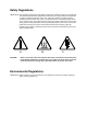
Safety Regulations IMPORTANT: This equipment incorporates high-voltage components. Adequate safeguards and interlocks have been designed into this equipment to reduce the risk of injury during normal operation. As with any electrical equipment of this kind, adequate ventilation must be provided to minimize exposure to heat, dust, ozone, and other emissions. The following labels will be found on the product.
Warranty Information The following warranty information pertains to equipment that is installed in the United States only. For equipment installed in countries other than the United States, the terms and conditions of the new equipment warranty will be provided by the Kodak company in the country in which the sale is finalized, or by a Kodak-appointed distributor in those countries where Kodak does not have direct sales representation.
Table Of Contents About This Guide..................................................................................................................................... Using This Guide.................................................................................................................... About Other Publications ...................................................................................................... Software Included With the Printer.................................................
Using the Printer Features .................................................................................................. 3-23 Accessing the Menu ..................................................................................................... 3-23 Unloading Paper ........................................................................................................... 3-23 Unloading the Supply and Takeup .........................................................................
4 Maintaining the Equipment ................................................................................................................... 4-1 Maintaining the Printer .......................................................................................................... 4-1 Daily Maintenance .......................................................................................................... 4-1 Calibrating the Printer ............................................................................
Appendix C: Additional Calibration Information ...................................................................................... C-1 Installing the Calibration Software........................................................................................ C-1 System Requirements ................................................................................................... C-1 Installation Procedure ...................................................................................................
Appendix E: Using the PHOTOSHOP Export Module ............................................................................ E-1 Installing the Export Module ................................................................................................. E-1 Hardware Requirements................................................................................................ E-1 Software Requirements .................................................................................................
About This Guide This is a User’s Guide for the KODAK PROFESSIONAL LED II Printer 20R. It provides step-by-step instructions for the operations you perform while using the Printer. It also includes procedures and information for operating, maintaining, troubleshooting, and calibrating the printer. Also included in this guide are instructions for installing and using the various software packages needed. This guide is intended for personnel who operate this system.
About This Guide About Other Publications The following publication is included with the printer: Quick Reference Guide for the KODAK PROFESSIONAL LED II Printer 20R and the KODAK PROFESSIONAL LED II Processor 20R–provides quick and easily accessible information for operating and maintaining the printer as well as answers to common printer problems and hints for operating the processor. Keep the Quick Reference Guide close to your printer.
About This Guide Getting Help from Kodak Your Kodak sales representative is the best source for information about setting up and operating your printer and for obtaining accessories and supplies. Please contact your Kodak sales representative if you have any questions. Kodak Sales Representative:___________________________ Representative’s Telephone Number:_____________________ K-Number:_________________________________________ In addition, for technical support in the U.S.
1 Introduction This chapter includes the following information about the KODAK PROFESSIONAL LED II Printer 20R: Product Description ...........................................................................................1-1 SCSI Interface .............................................................................................1-1 KODAK PROFESSIONAL LED II Printer 20R ............................................1-1 Installation and Service ..............................................................
Introduction Equipment Overview paper supply door Front View printer paper takeup door host computer and SCSI cable (not included) front slack loop door operator control panel densitometer (not included) front door Rear View connector ports circuit breaker back door back slack loop door power cord 1-2 September 2000
2 Using the System This chapter explains how to use the KODAK PROFESSIONAL LED II Printer 20R. It takes you from startup to shutdown. Topics include: Starting up the Printer ........................................................................................2-1 Calibrating the Printer ........................................................................................2-2 Obtaining Densities .....................................................................................
Using the System Calibrating the Printer You need to calibrate the printer when you start the system up each day. You also need to calibrate the printer when: • you change paper • print quality is questionable • the temperature at the site changes more than 5° F (2.8° C) • if running more than one shift, at the beginning of each shift If you are calibrating at any time other than during the daily startup procedure: Before you begin, make sure the printer is not receiving printing commands from the host.
Using the System The LED Calibration screen appears. 3. Click Go to start the calibration cycle. Go icon This icon highlights after you select Go Downloading LUTs and Sending Test Print highlights. If the configuration file specifies to Ask if processor is in control, the Process In Control dialog box appears. The processor is critical to printer calibration. You can calibrate the printer only if the processor is in control. Densitometers require calibration at regular intervals.
Using the System The Send LUT to Printer screen appears. NOTE: The highlighted LUT in the dialog box above is the most recent calibration LUT. 5. Click either Load Selected LUT or Load Custom LUT (or Cancel to cancel the calibration process). If you click Load Selected LUT, the system automatically downloads the highlighted LUT to the printer to create a test print.
Using the System The system automatically downloads the LUT file to the printer to create a test print. When the test print has been sent to the printer, the Scanning Processed Print with Densitometer status icon on the KODAK LED Printer Calibration screen is highlighted. Obtaining Densities Obtaining Densities from a File If the configuration settings include obtaining the density data from a file, the Waiting for Density File dialog box appears.
Using the System 3. Slide the lever on the densitometer to position 30. Align the edge of the test print with the lever on the densitometer. Gently feed the test print through the densitometer to scan the patches labeled “both”. Lever Test print If the test print is read successfully, several messages will appear in the status bar; the final message indicates that the densitometer values have been successfully received. Go to “Completing the Calibration.
Using the System 2. If calibration is out of tolerance, it may be necessary to run four or more iterations of the calibration cycle to achieve a successful calibration. If the print densities are out of tolerance, a graph appears, allowing you to select the type of data and planes that you want to see displayed. a. Click OK. The following list of options appears. Re-read the densitometer values is the most useful when the graphs show an unusual plot.
Using the System b. Select one of the four options to try to complete the calibration successfully. • If the Out of Tolerance dialog box appears again, repeat this step until you get a successful calibration; go to step 1. • If you cannot get a successful calibration, request help from a system administrator or service person. Making Prints You can make prints using the LED Printer 20R with a wide variety of applications that run on WINDOWS NT Computers and MACINTOSH Computers.
Using the System Hard Shutdown Use this method for shutting down the printer for an extended period of time (several days or longer). 1. Do a soft shutdown. See “Soft Shutdown” on page 2-8. CAUTION: Turn off the circuit breaker only after doing the soft shutdown. Otherwise, you could lose printer status information and will cause dark lines to appear in the middle of the prints if paper is loaded. 2. Turn off the circuit breaker on the back of the printer.
3 Operating Procedures This section provides the information you need to operate the KODAK PROFESSIONAL LED II Printer 20R. Topics include: Operator Control Panel (OCP) ...........................................................................3-2 OCP Key/Light Descriptions ........................................................................3-3 Status Messages .........................................................................................3-5 Loading Paper Into the Supply Cassette .............
Operating Procedures Operator Control Panel (OCP) The operator control panel (OCP) for the printer allows you to view and control: • • • • • • • current status of the printer current time of day paper specifications error and power status cancel, on/off line and menu functions parameters of the printer error messages current status LED indicator lights time of day LCD display Status: Initializing Status: Initializing Pages Waiting: Paper Width: Paper Supply: Paper Length: 2:43 Power Error Standby
Operating Procedures OCP Key/Light Descriptions Key/Light Key /LED Indicator Light Description/Function Start Start Key The Start key turns on the power for the printer when the printer has been shut down through the OCP. When using the OCP menu, the Start key functions as a Select key to select the highlighted item from the OCP menu. Cancel Cancel Key Pressing Cancel causes the job that is currently printing to quit.
Operating Procedures Menu The menu allows you to access other printer features. NOTE: To access the menu, the print queue must not have any pages waiting to be printed. 1. Press On/Off Line to take the printer offline. 2. Press Menu. Taking the Printer Offline This feature is useful when you need to access the printer OCP menu. When the printer is offline, it cannot send jobs to the processor or accept jobs from the host. To take the printer offline, press On/Off Line on the OCP.
Operating Procedures Status Messages Status messages display on the LCD display of the OCP to indicate the status or current state of the printer. Status Message/Printer State September 2000 Definition status: ON LINE – Ready The printer is idle and ready to accept jobs. status: ON LINE – Processing The printer is currently downloading or processing a job. status: ON LINE – Pages Deferred Pages are waiting and nothing is being downloaded.
Operating Procedures Loading Paper Into the Supply Cassette WARNING: Move the supply cassette from the printer to a table to load or unload paper. One 10- to 20-inch supply cassette and one 10- to 20-inch takeup cassette are included with the printer and are designed to hold rolls of paper that are 10-, 11-, 12-, 20-inch, and A4 widths. The supply cassette and takeup cassette are not interchangeable. Removing the Supply Cassette 1. Open the paper supply door. 2.
Operating Procedures Loading the Paper 1. Unlock the supply cassette locks. 2. Open the supply cassette. 3. If necessary, remove paper scraps from the core support assembly. 4. Remove the old core and support assembly from the supply cassette. NOTE: Keep the felt surfaces clean to prevent scratches on the paper. old core and core support assembly felt felt supply cassette locks 5. Remove the screw lock and the old cardboard core from the core support assembly. 6.
Operating Procedures TIP: Practice the following steps in the light with an empty cardboard core before you load a new roll of paper in the dark. CAUTION: Loading paper into the paper cassette must be completed in a darkroom with the lights off. 7. Position the paper so that the lead edge of the paper is away from you. 8. Insert the core support assembly from the left side into the roll of paper as shown. 9. Push the cardboard core toward the gear until it engages the detent. cardboard core detent 10.
Operating Procedures 12. Feed the lead edge of the paper through the slotted opening in the paper cassette. lead edge of the paper slotted opening image or emulsion side core support assembly (side without the gear) 13. Close the supply cassette and latch the supply cassette locks. NOTE: Be sure that the core support assembly rotates freely in the supply cassette and that the paper feeds freely. supply cassette lock NOTES: – When the paper cassette is locked, you can turn on the room lights.
Operating Procedures Attaching a Digital Paper Saver To save paper that is lost during the paper loading process when using the “1-Step Normal” paper loading option, you may install a digital printer paper saver (leader) to the lead edge of the roll of paper. Using the digital printer paper saver reduces the amount of paper lost from threading the printer by 5.5 feet as shown in the table below. Threading Method Amount of Unprintable Paper* Paper Leader 9 feet Digital Printer Paper Saver 3.
Operating Procedures 7. Fold the edges of the splice tape over the digital printer paper saver and the paper. 8. Cut a second piece of splice tape that is slightly smaller than the width of the paper. 9. Install the second piece of splice tape over the paper and the digital printer paper saver. second piece of splice tape 10. Turn the core support assembly to rewind the paper and digital printer paper saver into the supply cassette.
Operating Procedures Installing the Loaded Paper Supply Into the Printer 1. Open the paper supply door. 2. Empty the punch chad tray. See “Removing the Punch Chad” on page 4-2. 3. Align the slot on the bottom of the supply cassette with the plate on the bottom of the shelf and slide the supply cassette into place on the shelf. shelf Emulsion (image) side of paper (or paper saver) plate cassette clamp slot 4. Check that the gear on the supply cassette aligns and meshes with the gear on the printer. 5.
Operating Procedures 10. When the message “Feed paper into printer...” appears, pull the lead edge of the paper (or digital printer paper saver) out of the paper cassette and place the lead edge of the paper into the punch slots. right hole puncher lead edge of the paper (or paper saver) paper alignment guide gear on the cassette gear on the printer cassette clamp 11. Slide the lead edge of the paper under the feed roller and static brushes using both hands.
Operating Procedures Installing the Takeup Cassette Preparing the Takeup Cassette 1. Unlatch the takeup cassette locks and open the takeup cassette. 2. Remove the core support assembly. 3. Move the screw adjuster to the correct position for the paper size that you are loading. Pull the metal spring for the screw adjuster away from the gear and slide the screw adjuster to the correct position until it locks into place in the detent. 4. Slide the correct size cardboard core onto the core support assembly.
Operating Procedures 7. Install the core support assembly into the takeup cassette. See the instructions on the label on the top of the takeup cassette. NOTE: Make sure that the core support assembly is installed correctly in the cutouts of the takeup cassette. core support assembly cutout takeup cassette locks 8. Close the takeup cassette and latch the takeup cassette locks. NOTE: Be sure the core support assembly rotates freely in the takeup cassette. Installing the Takeup Cassette 1.
Operating Procedures 3. Install the takeup cassette onto the cassette support arms. IMPORTANT: Check that the bearings on the cassette are seated in the support arms.
Operating Procedures Cinching the Media to the Cardboard Core Do the following to cinch (attach) the media (paper or digital printer paper saver) to the cardboard core: Cinching the Digital Printer Paper Saver to the Cardboard Core Cinching Paper to the Cardboard Core (a) Hold the lead edge of the paper against the cardboard core and close to the flange. NOTE: Align the right edge of the paper with the flange, making sure that the paper is not skewed.
Operating Procedures Cinching Paper to the Cardboard Core (d) Turn the flange on the core support assembly until you have wrapped enough paper around the cardboard core to cinch it to the core. (e) Check that the right edge of the paper is still aligned with the flange and close to it. (f) Close and lock both sides of the takeup cassette. NOTE: The closed takeup cassette should move freely when you press down on the front of it. If necessary, reposition the takeup cassette to move freely.
Operating Procedures Unloading the Paper from the Printer The menu provides two options for unloading paper before the end of the roll is detected: • Unload Supply and Takeup—Automatically makes a cut between the exposed paper and the unexposed paper. The printer then winds the exposed paper and trailer into the takeup cassette and rewinds the unexposed paper into the supply cassette. NOTE: Approximately 27 inches of unexposed paper will not be rewound into the supply cassette.
Operating Procedures Removing the Takeup Cassette WARNING: Move the takeup cassette from the printer to a table to load or unload paper. 1. Open the takeup door. 2. Remove the takeup cassette from the printer by lifting it off of the support arms by the cassette handles. CAUTION: Move the takeup cassette to a darkroom before removing the exposed paper. See “Removing Exposed Paper from the Takeup Cassette” on page 3-21.
Operating Procedures Removing Exposed Paper from the Takeup Cassette 1. Remove the takeup cassette from the printer. See “Unloading the Paper from the Printer” on page 3-19. CAUTION: The following steps must be completed in a darkroom. 2. Unlatch the locks on the takeup cassette. lock (2) 3. Open the takeup cassette. 4. Tape the edge of the paper to the paper roll to prevent the paper from unwinding. 5. Remove the roll of paper from the takeup cassette.
Operating Procedures 6. Remove: • screw lock or flange • exposed paper from the core support assembly NOTE: After removing the screw lock, tap the screw lock end of the core to loosen the paper roll and make it easier to remove from the core support assembly. CAUTION: Keep the exposed paper in a darkroom or a dark bag until you process it. screw lock flange Adjusting the Paper Hole Punchers 1. Lift the arm for the right paper hole puncher. 2. Move the right paper hole puncher to the correct location.
Operating Procedures Using the Printer Features The following features are available from the menu on the OCP. Accessing the Menu 1. Press On/Off line to take the printer offline. 2. Press Menu. NOTE: If there are jobs waiting to be printed, the following options are available: • “Cancel” – exit • “Start” – prints jobs in the print queue and then accesses the menu • “Menu” – deletes jobs in the print queue and then accesses the menu Unloading Paper Follow one of the following procedures to unload paper.
Operating Procedures Shutdown and Restart Shutdown 1. Select “Shutdown” from the main menu on the OCP. 2. Select “Shutdown NOW?” This causes the printer to shut down operations and enter the standby mode. Restart 1. Select “Restart” from the main menu on the OCP. 2. Select “Restart NOW?” This causes the printer to immediately shut down operations and reboot. NOTE: This shutdown is not a soft shutdown and does not save the parameter settings that have been made since the previous startup.
Operating Procedures Paper Loading Options Lead Edge Paper Waste Paper Punches 1-Step Normal (factory default) 108 inches at all images 1-Step Save 62 inches at all images after the first exposure 2-Step Dark (new load) 35 inches at all images 2-Step Dark (rethread) 18 inches at all images after the first exposure 2-Step Light (new load) 47 inches at all images 2-Step Light (rethread) 47 inches at all images after the first exposure Load Option NOTE: For options in which the first expo
Operating Procedures Changing the Paper Loading Option When using the Paper Loading Feature, you should select the paper load option before you load paper into the printer. However, you can change the paper load option at any time. If you change the loading option: • before selecting “Unload Takeup and Rethread” from the main menu on the OCP, the paper will follow the rethreading procedure for the loading option that you selected.
Operating Procedures Setting the Length of the Paper Trailer This value determines the amount of unexposed paper to be added to the trail edge of the paper wound into the takeup cassette when you send an “Unload Takeup and Rethread” command. 1. Select “Setup” from the main menu on the OCP. 2. Select “Printer”. 3. Select “Trailer”. 4. Use the Up and Down Arrows to select a new trailer length (from 0 to 3000 pixels). 5. Press Select to select/set the new value. 6.
Operating Procedures Gutter Punch—controlled by a command sent from the host computer. See “Changing the Gutter Width” on page 3-35. This punch is on the same side as the cut punch and is 0.25 to 1.0 in. inside of the image (depending on the value of the gutter width). Cut and Order Punches on Same Side of the Paper outline of paper outline of image 0.25 in. cut punches white order punch 0.25 in.
Operating Procedures Using the Automatic Roll ID The printer has the ability to automatically print a roll identification (roll ID) at the beginning of each roll. When this feature is enabled, the roll id will be printed every time paper is loaded into the printer and every time the paper is rethreaded (for example: when “Unload Takeup and Rethread” is selected). The roll ID includes the date, time, and roll ID number. The date and time are the date and time that the roll of paper was loaded.
Operating Procedures Setting the Page Starts Value 1. Select “Setup” from the main menu on the OCP. 2. Select “Printer”. 3. Select “Page Starts”. 4. Select the Page Start you want to modify. 5. Use the Up and Down Arrows to select a new Page Start value. 6. Press Select to select the new value. 7. Select “Exit” to return to the previous menu on the OCP.
Operating Procedures 3. Adjust the page starts value to the calculated pixel value. If the white border is on the: • back edge—reduce the page start value by the pixel value • front edge—increase the page start value by the pixel value distance A cut edge distance B cut edge IMPORTANT: The page start value for each paper width is different. Resetting the Defaults Resetting the Parameters This procedure resets the parameters of the printer to the factory setup (default) values.
Operating Procedures Resetting the Copyright Detection LUTs This procedure resets the Copyright Detection LUTs stored in nvram to the factory setup (default) values. To indicate that the values have been reset to the factory setup values, the word “done” is displayed in parenthesis after “Reset Copyright LUTs To Factory” on the menu. 1. Select “Setup” from the main menu on the OCP. 2. Select “Defaults”. 3. Select “Reset Copyright LUTs to Factory”. 4. Select “Exit” to return to the previous menu on the OCP.
Operating Procedures Selecting A Modem Resetting the Modem Port 1. Select “Setup” from the main menu on the OCP. 2. Select “Ports”. 3. Select “Modem (Diag)”. 4. Select “Reset Port”. 5. Select “Reset Modem Port Now”. NOTE: This causes the modem port to be set to its original factory setting. 6. Select “Exit” to return to the previous menu on the OCP. Checking the Modem Presence NOTE: This causes the printer to query the modem port for the presence of a modem. 1.
Operating Procedures Setting the Current Day 1. Select “Setup” from the main menu on the OCP. 2. Select “Time”. 3. Select “Day”. 4. Use the Up and Down Arrows to select a new day. 5. Press Select to select/set the new value. 6. Select “Exit” to return to the previous menu on the OCP. Setting the Amount of Space Between Images The Page Spacing feature allows you to determine the amount of white space the printer adds between the images.
Operating Procedures Changing the Units of Measurement for Paper Sizes 1. Select “Setup” from the main menu on the OCP. 2. Select “Printer”. 3. Select “More”. 4. Select “Units”. 5. Select “Units” again. 6. Use the Up and Down Arrows to select either “English” or “Metric”. 7. Press Select to select/set the new value. 8. Select “Exit” to return to the previous menu on the OCP.
Operating Procedures Setting the Copyright Detection Feature The Copyright Detection feature is designed to protect the copyrighted images of professional photographers. This feature is applied to copyrighted images to prevent images from being duplicated. 1. Select “Setup” from the main menu on the OCP. 2. Select “Printer”. 3. Select “Copyright Detection”. 4. Use the Up and Down Arrows to select “Always On”, “Always Off” or “Host Select”.
Operating Procedures Handling and Storing the Paper Follow the instructions included with the paper for storing and handling the paper properly. IMPORTANT: Avoid storing paper in low humidity conditions. Storing Paper by Using the Soft Shutdown Feature The Soft Shutdown feature (see “Soft Shutdown” on page 2-8) causes the rollers to automatically reverse to rewind the lead edge of the paper to the first metering roller during the soft shutdown process.
Operating Procedures In the printer, the paper is punched before the print job is printed. Since the punch is upstream of the printing, the first job of the next print cycle may be punched when positioning the paper for the current print cycle (to reduce waste). If the print job is sent down to the printer with the Buffered/Deferred option, this indicates to the printer to wait until it has a full buffer before printing. A full buffer is 26.5 to 33 inches.
4 Maintaining the Equipment This chapter includes information you will need to maintain the KODAK PROFESSIONAL LED II Printer 20R. The topics are as follows: Maintaining the Printer .......................................................................................4-1 Daily Maintenance .......................................................................................4-1 Calibrating the Printer ...........................................................................4-1 Removing the Punch Chad ...
Maintaining the Equipment Removing the Punch Chad Remove and dispose of the punch chad from the punch chad tray in the paper supply area every time you add a new roll of paper to the printer.
Maintaining the Equipment Periodic Maintenance Replacing the Air Filter The air filter under the shoe should be replaced approximately every 3 months. 1. Open the front door of the printer. 2. Pull back the spring fingers. 3. Remove the air filter. 4. Install a new air filter. For parts ordering information, see “Supplies” on page A-1.
5 Diagnostics and Troubleshooting This chapter describes the error messages for the KODAK PROFESSIONAL LED II Printer 20R and offers information for troubleshooting. The information in this chapter includes: Printer Error Messages ......................................................................................5-1 Manual or Automatic Reinitialization ...........................................................5-1 Printer Paper Path ........................................................................
Diagnostics and Troubleshooting Printer Paper Path The paper path through the printer is illustrated below. Use this information when troubleshooting the printer. WARNING: Do not touch the carriage. Use the translator knob to move the carriage. CAUTION: Do not use sharp objects on the shoe. Rotate the flop preventer knob to move the flop preventer out of the way before moving the carriage with the translator knob.
Diagnostics and Troubleshooting Printer Error Messages If the error message continues to occur after implementing the possible solutions from the table below, call your service person. Error Code Error Message Possible Cause Possible Solution 1 not initialized Attempting to perform a function before the printer has initialized. Reinitialize the printer. 2 initializing err Attempting to perform a function during the initialization process.
Diagnostics and Troubleshooting Error Code 5-4 Error Message Possible Cause Possible Solution 18 unexpected OCP reply The 300 board sent an unexpected message to the 200 board. Call for service. 20 pec service mode The service switch for the 200 board is on, enabling on-board LEDs that can cause fogging. Call for service. 21 opc service mode The service switch for the 300 board is on, enabling on-board LEDs that can cause fogging. Call for service.
Diagnostics and Troubleshooting Error Code Error Message Possible Cause Possible Solution 66 paper jam in shoe Jam detect sensor detected jammed paper at the shoe entrance. • Remove jammed paper and unload the takeup cassette. • If you are using a digital printer paper saver and the paper jammed before it was cinched in the takeup cassette, wipe the paper saver with a damp, cloth to remove dust and static electricity. • Reload the paper.
Diagnostics and Troubleshooting Error Code 5-6 Error Message Possible Cause Possible Solution 80 paper at shoe entr not detected During paper loading, the lead edge of the paper was not detected at the shoe entrance sensor within the expected amount of time. Load the paper in less time. 81 unexpected paper at knife • Paper jam occurred as paper was being reversed from the knife to the end of roll and paper was detected at the knife instead of at the shoe entrance.
Diagnostics and Troubleshooting Error Code Error Message Possible Cause Possible Solution 96 shoe exit nip made not detected The shoe exit nip made switch was not detected after moving the shoe exit nip to the nip made position. Check for a paper jam in the shoe exit nip area. 97 unexpected deflector nip made The deflector nip made switch was detected after moving the deflector to the up position. Check for a paper jam in the deflector nip area.
Diagnostics and Troubleshooting Miscellaneous Printer Error Messages Miscellaneous error messages indicate that a problem with the printer has occurred that may or may not require you to call your service person. Error Code 5-8 Error Message Possible Cause Possible Solution 256 door open, please close The paper supply door was left open. Close all doors. 257 machine control initialize error The printer did not initialize. Reinitialize the printer and call for service.
Diagnostics and Troubleshooting Clearing Paper Jams 1. Open the paper supply door. 2. Cut the paper with a scissors or knife. cut here 3. Open the takeup door. 4. If the paper has not already been cut at the takeup cassette area, cut the paper with a scissors in front of the takeup cassette. cut here 5. Move the right paper punch away from the paper.
Diagnostics and Troubleshooting 6. Pull the paper out of the printer from the paper supply area. NOTE: Follow the instructions for clearing paper jams on the paper supply door label. CAUTION: Do not use sharp objects when clearing paper jams. Do not leave small pieces of paper in the printer. 7. If necessary, wind the paper into the takeup cassette. 8. Reload the paper. 9. Close the paper supply door.
Diagnostics and Troubleshooting Troubleshooting Observable Errors Observation A print has a line on it. Possible Cause Possible Solution The circuit breaker was turned off when paper was in the shoe. • Do not turn off the circuit breaker when paper is in the shoe. • Do a shutdown prior to turning off the circuit breaker. The printer was disturbed or bumped during the print cycle. Do not disturb or bump the printer during the print cycle. The prints have a repeated unfocused pattern on the edges.
Diagnostics and Troubleshooting Observation The boarders on the prints are not the right size. Possible Cause Possible Solution The host software’s image positioning is not correct. Refer to the instructions for image positioning in the manual for the host software. The page start parameter may be incorrect. See “Using Page Starts” on page 3-29. • The paper is not loaded correctly in the paper cassette. • The paper supply cassette clamp is not secured correctly.
Diagnostics and Troubleshooting Observation Possible Cause The supply or takeup door will not close. The latch on the door was pushed in (flush with the door) when the door was closed with too much force. Possible Solution Pull the latch back to its normal position with scissors and close the door with a normal amount of force. latch Additional Troubleshooting Tips for the Printer September 2000 • Be careful to correctly load, seat, and thread the paper into the paper cassettes.
Diagnostics and Troubleshooting Calibration Troubleshooting This section describes the problems that you may occasionally have when using the KODAK Device Calibration Software or the Calibration Software for the KODAK PROFESSIONAL LED II Printer. It also identifies the probable causes for these problems and provides solutions for correcting these problems. Calibration Graph The graph below is an indication that the calibration performed was out of tolerance.
Diagnostics and Troubleshooting Error Code Error Code /Status Message Possible Cause/Subsystem Possible Solution 6 The following file already exists:_filename_. The system is trying to save to a file that already exists. • Delete the existing file. • Change the filename. 7 There is not enough space to create:_filename_. The system is trying to save a file but there is not enough disk space. Remove any unnecessary files to increase free disk space. 8 There are too many files to open _filename_.
Diagnostics and Troubleshooting Error Code Error Code /Status Message 111 There is insufficient memory for the requested operation on device:_devicename_. The application does not have enough memory to complete the operation. Close the other applications and unnecessary windows. 112 A communications time-out occurred during operation on device:_devicename_. The connection between the printer and host computer was lost. Check that all of the cables are properly connected.
Diagnostics and Troubleshooting Error Code Error Code /Status Message Possible Cause/Subsystem Possible Solution 202 The following parameter is invalid:_parametername: _parametervalue_. An internal error occurred with the software. • Restart the application. • If problem continues, call for service. 203 The function is not supported by the class. An internal error occurred with the software. • Restart the application. • If problem continues, call for service.
Diagnostics and Troubleshooting Error Code Error Code /Status Message Possible Cause/Subsystem 704 CalToleranceFile:: initialize must be called first. An internal error occurred with the software. • Restart the application. • If problem continues, call for service. 801 Could not find row:_row_. An internal error occurred with the software. • Restart the application. • If problem continues, call for service. 802 Could not find column:_column_. An internal error occurred with the software.
Diagnostics and Troubleshooting Error Code Error Code /Status Message 923 An error occurred during the loading of a printer. Please check to make sure the file chosen was of the correct type and/or format. An error occurred during the loading of a printer. Check that the file chosen was of the correct format or type. 924 No printer loaded. The operator has not yet opened a printer. Open a printer. 941 The height and width values do not agree with the size of the target file.
Diagnostics and Troubleshooting Error Code Error Code /Status Message Possible Cause/Subsystem Possible Solution 1202 Error:_error_from densitometer. Unexpected error was returned from the densitometer. Calibrate the densitometer. If the problem continues, check the manual for the densitometer. 1203 Error: Number of patches seen by densitometer is incorrect. Unable densities on densitometer. Try adjusting frame counts or reread the density patches on the densitometer.
Diagnostics and Troubleshooting Non-Numeric Error Messages Error Message Possible Cause/Subsystem An underrun error occurred during communications to the following device. • The cable between the printer and the host computer is worn. • One or more of the connections between the printer and the host computer has malfunctioned. • Check that all of the cables are properly connected. • Check the cables and connections between the printer and the host computer for wear and if necessary, replace them.
Diagnostics and Troubleshooting Getting Additional Help Your Kodak Sales Representative is the best source for information about the KODAK PROFESSIONAL LED II Printer 20R. In addition, technical support is also available in the United States. Call Kodak’s Technical Assistance Center at 1-800-3Kodak3 from 8:00 a.m. to 11:00 p.m. Eastern Standard Time on regular business days. Have your printer’s K-Number ready. The K-Number label is attached to the front of the printer, next to the operator control panel.
Appendix A: Ordering Supplies This appendix includes ordering information for Kodak accessories, supplies, paper, leaders and splice tape, and publications. Accessories Purchase these items through Kodak. Qty/Size Catalog Number X-RITE DTP—36 Densitometer 1 196–1119 US ROBOTICS-SPORTSTER 28.
Ordering Supplies Standard (U.S.) Paper Purchase these items through your Kodak representative. Surface Types* Size KODAK PROFESSIONAL Digital Paper E, F, or N 10 in. x 262 ft. KODAK PROFESSIONAL Digital Paper E, F, or N 10 in. x 574 ft. KODAK PROFESSIONAL Digital Paper E, F, or N 11 in. x 262 ft. KODAK PROFESSIONAL Digital Paper E, F, or N 11 in. x 574 ft. KODAK PROFESSIONAL Digital Paper E, F, or N 12 in. x 262 ft.* KODAK PROFESSIONAL Digital Paper E, F, or N 20 in. x 262 ft.
Ordering Supplies Leaders and Splice Tape Purchase these items through the appropriate vendor. Qty Vendor Catalog Number KODAK 1-Inch Splice Tape 2 Kodak 168-1311 10-Inch Digital Printer Paper Saver 10 Liberty Photo Products* L-1210 11-Inch Digital Printer Paper Saver 10 Liberty Photo Products* L-1211 20-Inch Digital Printer Paper Saver 10 Liberty Photo Products* L-1220 Item * Call 1-800-572-3600 in the United States to order items through Liberty Photo Products.
Appendix B: Specifications This appendix includes specifications and site requirements information for the printer. Printer Specifications Dimensions and Weight Width Length 102 cm (40 in.) 149 cm (58.5 in.) Weight 499 kg (1100 lbs) 517kg (1140 lbs)–with paper To move the printer through a 91 cm (36 in.
Specifications Site Requirements Operator and Service Access When fully assembled the equipment requires a minimum of 91 cm (36 in.) on each side to allow sufficient access for normal operator maintenance and for service. 2.2 meters _ + .3 meters (86 in. + _ 12 in.) 15A (36 in.) *.91 meters minimum 1.5 meters (60 in.) 2.9 meters (114 in.) Printer .91 meters (36 in.) minimum .91 meters (36 in.) minimum .91 meters (36 in.) minimum 3.7 in.) 3.8 meters meters(146.5 (149 in.
Specifications Electrical The KODAK PROFESSIONAL LED II Printer 20R is manufactured to operate within one of the following sets of power constraints or can be configured to do so by a Kodak representative: Nominal Voltage/Frequency 200 - 240V, 15A, 50/60 Hz, 1 phase* Voltage Range 190 - 254V, 47 - 63 Hz, 1phase, 15 A (Automatic Sensing)** Power Consumption Less than 2.4kVA * Phase selection must be completed at the factory or by a trained Kodak representative. * *Outside the U.S.
Specifications Power Outlets A separate, dedicated power line with a 208 V, 15 amp dedicated receptacle is required for the printer. The outlets should meet the following standards: Item amperage wire size phase Printer Standard 15 amp 14 gauge or larger 1 (single) receptacle NEMA5—N6/15 impedance between ground and neutral wires less than 2 ohms voltage drop across the circuit breaker less than 0.1 volts distance between receptacle and equipment 1.5 m (5.0 ft.
Specifications Line Voltage The printer operates satisfactorily over a range of voltages around the nominal voltage. The local utility company is required to deliver power usually within ±10% of the rated value to the main distribution panel in the building. Voltage then drops from there to the outlets where the equipment is connected. The total voltage drop is a function of the following factors: • The composition of the conductor material in the wire.
Specifications Power Receptacles (U.S.
Specifications Printer Power Receptacles (Europe) OB OA OC IG IN Computer system branch circuit panel CEE (7) 250,16A L N 16A (1.
Specifications Telephone line A telephone line (with a RJ11C modular phone jack) must be installed within 3 m (10 ft.) of the printer to support the remote diagnostics. We recommend a high-grade analog service line. Densitometer An X-RITE DTP—36 Densitometer is required to calibrate the printer and for process control. It is available through Kodak. See “Accessories” on page A-1. SCSI Cable A single-ended or differential-ended SCSI cable is required to connect the host computer to the printer.
Appendix C: Additional Calibration Information The topics covered in this section include: • • • • Installing the Calibration Software An overview of the KODAK Device Calibration Software Advanced Features of the LED II Calibration Software Installing the Densitometer IMPORTANT: For the step-by-step procedure to calibrating the printer, see “Calibrating the Printer” on page 2-2.
Additional Calibration Information Installation Procedure 1. Place the supplied CD-ROM in your CD-ROM drive. 2. When the Browser appears, select LED Printer. MACINTOSH Version Under “Download File,” select LEDCalAppVn (n is the current version number). LEDCalAppVn is saved to your desktop. WINDOWS NT Version Under “Download File,” select KPRO Calibration Utilities. You can either save the installation file to a hard drive or run it directly from the Internet.
Additional Calibration Information 6.
Additional Calibration Information Kodak Device Calibration Software The Kodak Device Calibration Software is used to launch the Calibration Software for the 20P and 20R Printers and to launch calibration software for other devices such as other printers and scanners. NOTE: Most of the windows displayed in this chapter are from the WINDOWS NT Version of the software. The windows for MACINTOSH Computers are similar.
Additional Calibration Information The table below defines the functions and their corresponding icons on the main window of the KODAK Device CalibrationSoftware.
Additional Calibration Information Starting the Kodak Device Calibration Software Load the Calibration Software according to the table below. (If needed, see “Installing the Calibration Software” beginning on page C-1.) MACINTOSH Version 1. Open the folder that contains the files for the calibration application. 2. Click on the icon for KODAK Device Calibration. WINDOWS NT Version Select: Programs/Eastman Kodak/ KPRO Applications/ Kodak Universal Calibration Utility from the WINDOWS NT Start menu.
Additional Calibration Information The Create a New Device dialog box appears. 2. Enter the correct device settings. Use a unique identifying word for the device name. NOTES: The default SCSI ID for the printer is 5. The printer’s OCP menu displays the current SCSI ID for the printer. Make sure the Device Type field matches the type of printer that is being calibrated (for example: Digital LED II 20P). 3. Click OK to accept the changes.
Additional Calibration Information Editing the Log Settings To change the log settings for the KODAK Device Calibration: 1. Deselect all devices on the KODAK Device Calibration screen and click the Edit icon. Edit icon All devices must be deselected The Edit Configuration dialog box appears: 2. Edit the device settings as needed or click Default to refresh the screen with the default settings.
Additional Calibration Information Updating a Device To update or change the device name or the SCSI ID for any device: 1. Select the device by clicking once on the device icon on the KODAK Device Calibration screen. Edit icon Device icon 2. Click the Edit icon. The Update a Device dialog box appears. 3. Enter the correct device settings. The options for the device settings include: Device Setting Options Device name Enter the name that you want to give to the device.
Additional Calibration Information Deleting a Device To delete a device from the KODAK Device Calibration Software screen: 1. Select the device by clicking on the device icon. Cut icon Device icon 2. Click the Cut icon. The following dialog box appears: 3. Click Yes to delete the files and directories for the selected calibration device. (Click No to stop the deletion process.
Additional Calibration Information Advanced Features of the LED II Calibration Software The Calibration Software for the KODAK PROFESSIONAL LED II Printer 20P/20R provides automated neutral density printer calibration and is designed to be used without assistance from technical experts. The advanced calibration features provided by this product enable you to customize the calibration of the printer.
Additional Calibration Information Value Graph C-12 September 2000
Additional Calibration Information Difference Graph September 2000 C-13
Additional Calibration Information History Graph To view calibration graphs: 1. From the KODAK Device Calibration screen, double-click the device for which you want to view graphs.
Additional Calibration Information The LED Calibration Application screen appears. Graphs icon 2. Click the Graphs icon. One of the graphs appears; normally it is the Value graph. 3. Select the Graph Type that you want to view. When the graph appears, select the type of data and planes that you want to see displayed. NOTE: The graph will be blank if the printer has not been calibrated.
Additional Calibration Information Sending LUTs The Send LUT to Printer feature allows you to overwrite the current LUT in the printer. You can create a valid printing LUT using an ASCII text editor. This option sends the selected LUT to the printer, overwriting any existing LUT. To send a LUT to the Printer: 1. From the KODAK Device Calibration screen, double-click the device for which you want to send a LUT. The LED Calibration Application screen appears. Send LUT icon 2. Click the Send LUT icon.
Additional Calibration Information The Send LUT to Printer dialog box appears. 3. Select one of the LUTs from the dialog box and click Load Selected LUT or click Load Custom LUT and follow the prompts to load a custom LUT. The LUT is downloaded to the printer, overwriting the current LUT. Sending Targets The Send Target feature enables you to send any properly formatted target file to the printer without performing a calibration.
Additional Calibration Information The LED Calibration Application screen appears. Send Test Target icon 2. Click the Send Test Target icon. The Send Target to Printer dialog box appears. (Both the Windows NT and Macintosh versions are shown here.
Additional Calibration Information NOTE: Windows NT users can click Browse to select another file name. The Open dialog box appears. Select the file name you want, then click Open. MACINTOSH Version 3. Enter the desired settings and click OK to save the settings (or Cancel to keep the previous settings). The selected test target is sent to the printer.
Additional Calibration Information Editing the Calibration Configuration The Edit Configuration feature allows you to change the printer’s calibration configuration attributes. However, it is recommended that you use the default settings for these attributes for most operations. The settings should only be changed for the most advanced operations. Edit Configuration consists of a set of six tabbed screens—each with related configuration attributes.
Additional Calibration Information The Edit Configuration screen appears with the Procedure tab displayed. Edit Configuration Screen for WINDOWS NT Systems Edit Configuration Screen for MACINTOSH Systems 3. To navigate among the tabs, click the tab you want and follow the instructions for updating the information for that tab.
Additional Calibration Information IMPORTANT: Whenever you click OK, the software assumes ALL changes to the Edit Configuration are complete and the Edit Configuration screen closes. Similarly, you can click Cancel at any time while the Edit Configuration screen is open; any changes you made to any of the tabbed information are canceled and the Edit Configuration screen closes.
Additional Calibration Information To edit the configuration information on the Procedure tab: 1. Use the drop-down lists to change the Procedure information as needed. 2. If you have completed all editing of configuration information (including information on the other tabbed screens), click OK to save the changes and close the Edit Configuration screen. NOTE:Click Cancel to cancel all changes made to the Edit Configuration screen and close the Edit Configuration screen. 3.
Additional Calibration Information Editing Information on the Density Source Tab The Density Source tab specifies how the calibration application is to receive density data. The values displayed in the example are the default settings. Density Source Attribute Description Density Source Indicates the source (densitometer or file) of the density data. Density Source Port Indicates the name of the RS-232 port that the densitometer is connected to. This port is the source of the density data.
Additional Calibration Information Editing Information on the Aim Tab The Aim tab specifies: • whether the aims used for calibration are to be Density Aims or Lightness Aims • • whether to apply the Channel-Independent Matrix which table to use if Copyright Detection is functional The values displayed in the example are the default settings. Attribute Description Desired Aim Indicates whether to use Density Aims or Lightness Aims for calibration.
Additional Calibration Information Editing Information on the History Tab The History tab specifies information about maintaining calibration history data. The values displayed in the example are the default settings. Attribute Description Keep History For (days) Indicates the number of days that the calibration LUT, print LUT, density data and LUT history information (LED trend data) are to be kept. Information older than the specified number of days will be deleted.
Additional Calibration Information Editing Information on the Paper Tab The Paper tab allows you to specify the paper being calibrated. The value displayed in the example is the default setting. Attribute Paper Type Description Select either KODAK PROFESSIONAL Digital III Paper (Digital III) or KODAK PROFESSIONAL Digital PT 2976 Paper (2976). To edit the configuration information on the Paper tab: 1. Change the Paper Type if needed. 2.
Additional Calibration Information Editing DP2 Information (WINDOWS NT Systems) When you click the DP2 tab of the Edit Configuration screen, the following tabbed screen appears. The values displayed in the example are the default settings.
Additional Calibration Information Editing KPIS Information (Macintosh Systems) If you are using the calibration output files with the KPIS system, it is necessary to activate KPIS and assign a filename and location to the output file. When you click the KPIS tab of the Edit Configuration screen, the following tabbed screen appears. The values displayed in the example are the default settings.
Additional Calibration Information The display shows the Edit Configuration screen with the default settings for KPIS Location and KPIS Filename. 2. To change the directory for the KPIS file: a. Click KPIS Location. The display shows the Select KPIS Folder dialog box. b. If needed, browse to find the folder you want. c. Click on Select “directoryname” (the example above shows Select “KodakLED”).
Additional Calibration Information The display shows the updated Edit Configuration screen with updated File Location of CalDisk:CompositeMachine:Tables:KodakLED. Completing the Edit Configuration When finished, click OK to save the attributes. (Click Cancel to exit the screen without saving your changes. Macintosh users: you can click Default at any time to reset the attributes to their factory defaults and then click OK to save the defaults.
Additional Calibration Information Creating a Density File for Use with Calibration During calibration, you have the option of obtaining density data from a file or by scanning a processed test target through an X-RITE DTP 36 densitometer. The option is determined by the entry in the calibration configuration file. If the configuration file is set up to receive density data from a file and you are creating the file: 1. Scan the print into your densitometer. 2.
Installing the Densitometer This section describes how to install the X-RITE DTP 36 Densitometer, including changing some of the attributes on the Edit Configuration screen to accommodate the densitometer. IMPORTANT: The supported densitometers use a RS-232 interface for communication to the host. Each platform uses different designations to identify the RS-232 ports. To install the densitometer: 1.
Appendix D: Using the Image Print Server Software This section describes how to use the KODAK PROFESSIONAL Image Print Server Software for WINDOWS NT Workstation 4.0 Systems with the KODAK PROFESSIONAL LED II Printer 20P (20P Printer) and the KODAK PROFESSIONAL LED II Printer 20R (20R Printer).
Using the Image Print Server Software Installing the Software 1. Insert the IPS Software CD into the CD-ROM drive. 2. Double-click on the Setup.exe icon. 3. Follow the on-line instructions to complete the installation. The default installation location for the software is “C:\Eastman Kodak\KPro Applications\KODAK PROFESSIONAL Image Print Server.” In addition to the application, the installation procedure also installs a tone scale correction LUT that may be used by the IPS application.
Using the Image Print Server Software Suspending and Resuming When the IPS application begins execution, it searches the current directory for its preferences file, KIPSpref.dat. If this file is not found, the application begins execution in the “suspended” state as if the Suspend button was pressed. While suspended, the application does not communicate with the printer for any reason. As a result, the status bars on the application will not reflect the accurate state of the printer.
Using the Image Print Server Software Enqueue Example 1.
Using the Image Print Server Software The Enqueue dialog box appears. 2. Type a file name into the Image File text box or click the Browse button. 3. Click OK to close the Enqueue dialog box and to insert the specified file into the print queue. NOTE: You cannot enqueue a file that is being downloaded to the printer. You must wait the file has completed downloading before you can access the file.
Using the Image Print Server Software Dialog Boxes and Print Options This section describes the dialog boxes and print options for the KODAK Image Print Server Software.
Using the Image Print Server Software Option Descriptions The main window allows you to choose the following options: Menu Access Button Icon Description/Function File Enqueue Displays the Enqueue dialog box and allows you to insert a new image into the print queue. File Dequeue Allows you to remove the top entry from the print queue. File Flush Allows you to delete all entries from the print queue. Server Suspend Suspends the operation of the application.
Using the Image Print Server Software Enqueue Dialog Box Option Descriptions The selections/options that you can make from the Enqueue dialog box include the following: Image File Text Box— you may type in a name or browse the directory structure. OK—closes the dialog box and inserts the specified file into the print queue. Cancel—closes the dialog box without saving any changes. Copies—the number of copies to print.
Using the Image Print Server Software Source Directory Preferences Dialog Box Option Descriptions The selections/options that you can make from the Server Default dialog box are: OK—closes the dialog box and saves the specified values. Cancel—closes the dialog box without saving any changes. Source Directory—the directory/folder where the TIFF application will look for the TIFF images to arrive. Type a directory name or click the browse button.
Using the Image Print Server Software Initialize Default Parameters Dialog Box Description This dialog box appears if you press the Resume button (or activated through the menu bar) before the Source Directory Preferences have been initialized. File Format Details The data portion of the TIFF file must contain RGB byte interleaved data. The specific TIFF tags that are supported are shown below. Supported Tags The Image Print Server supports the TIFF tags listed below.
Appendix E: Using the PHOTOSHOP Export Module This appendix describes how to use the Export Module for PHOTOSHOP on MACINTOSH Systems with the KODAK PROFESSIONAL LED II Printer 20P. The Export Module allows you to export prints from PHOTOSHOP to a 20P Printer. The Export Module allows you to: • • Scale an image by 200% Center an image within a user specified border Installing the Export Module This section explains how to install the Export Module on your MACINTOSH system.
Using the PHOTOSHOP Export Module Installing the Software 1. Open the Adobe Photoshop folder on your computer. The Adobe Photoshop window appears. It should look similar to the one shown below. 2. Insert the Host Software CD (included with your printer) into the CD drive. 3. Double-click the CD icon on your desktop. 4. Double-click on the Macintosh folder. 5. Double-click the KODAK LED Printer Export Module folder. The KODAK LED Printer icons appear.
Using the PHOTOSHOP Export Module 6. Click and drag the KODAK LED Printer plug-in icon and Media Files over the Adobe Photoshop Plug-ins folder and release the mouse button. A copy progress dialog box appears as the folders and files are copied. 7. Click and drag the remaining files from the KODAK LED Printer window to a Utility folder or another location on your system. Printing Images Do the following to print an image. See page 6 for details. 1. Start PHOTOSHOP and open an image file.
Using the PHOTOSHOP Export Module To select another printer: 1. Click Select. The Select a KODAK LED Printer dialog box appears. 2. Select the printer by clicking the appropriate button. 3. Click OK.
Using the PHOTOSHOP Export Module The KODAK LED Printer main dialog box appears. 4. Make the remaining print option choices to meet the needs of your print job from the KODAK LED Printer dialog box. See “Dialog Boxes and Print Options” on page E-6 for more information. 5. Click Print. A PHOTOSHOP progress dialog box appears. To cancel printing, press the command key and type a . (period). If the cancel command is ignored, select Cancel Printing in the PHOTOSHOP progress dialog box.
Using the PHOTOSHOP Export Module Dialog Boxes and Print Options This section describes the dialog box that allows you to specify print options. KODAK LED Main Dialog Box Option Descriptions The Printer group box allows you to choose the following options: Select—opens the Select a KODAK LED Printer dialog box. Status—opens the Printer Status dialog box. Defer Print—instructs the printer to “defer” printing the image until the printer queue is full.
Using the PHOTOSHOP Export Module Other options The other selections you can make from the KODAK LED Printer main dialog box include the following options: Copies— allows you to specify the number of copies. Up to 99 copies can be printed at a time. The default is 1. Print—sends the job to the printer. Cancel—closes the dialog box without printing the image or saving changes. Help—opens a Help dialog box so you can find information about the Export Module within the software program.
Using the PHOTOSHOP Export Module Page Layout Attributes Option Descriptions The Page Layout Attributes group box allows you to manipulate the position of the image on the page. Center—centers the image within the specified border. Border—specifies the number of pixels of white border that should surround the image on the page. This box is only active when the center box (above) is checked. Scale 200%—allows you to scale the image 200%.
Using the PHOTOSHOP Export Module Option Descriptions The following are descriptions of the options in the Select a KODAK LED Printer dialog box: Update—refreshes the screen and replaces any information that has changed. Cancel—closes the Select a KODAK LED Printer dialog box without changing the current printer selection. OK—closes the Select a KODAK LED Printer dialog box. Printer Status Dialog Box Selecting the Status button to open the status dialog box in the KODAK LED Printer main dialog box.
Using the PHOTOSHOP Export Module Option Descriptions The following are descriptions of the options in the Printer Status dialog box: Printer Information—describes the state of the selected proofer. The color of the status field appears black if the proofer is idle, red for error conditions, and blue if the printer is processing or printing. Information includes the printer model, print media, print location, amount of RAM installed on your system, and the printer version number.
Using the PHOTOSHOP Export Module There are no printers found attached to the host computer. Check the connections and power to each printer. Check that the connections to each printer, including the SCSI cables and power cables, are properly connected. The previously selected SCSI printer is no longer available or has been changed. This message occurs if the SCSI printer that you selected is no longer available. Click OK to open the print dialog box.
Index A access, operator and service B-2 activate DP2, attribute in configuration file C-28 activate KPIS, attribute in configuration file C-29 adding a calibration device C-6 to C-7 air filter, replacing 4-3 arrow keys 3-3 Asian helpline number 5-22 automatic roll ID 3-29 automatic initialization, printer 5-1 B bar coding 3-38 borderless prints 3-30 buffered jobs, printing 3-4 C calibrating the printer, procedure 2-2 calibration configuration C-20 to C-31 aim tab C-25 density source tab C-24 DP2 tab C-28
Index error messages Export Module E-10 miscellaneous 5-8 printer 5-3 error, light 3-3 European region helpline number 5-22 Export Module dialog boxes and print options E-6 installing E-1 troubleshooting E-10 exposed paper, removing 3-21 F features, accessing 3-23 file formats C-32 density data C-32 IPS D-10 filters, air 4-3 G getting additional help 5-22 graphing, attribute in configuration file C-22 graphs, viewing C-11 difference C-13 history C-14 value C-12 gutter punch 3-27 H hard shutdown 2-9 hard
Index O OCP.
Index supply cassette installing 3-12 loading paper 3-6 removing 3-6 T takeup cassette installing 3-14 removing 3-20 removing exposed paper 3-21 target pad reads, setting 3-32 test target densitometer reading 2-5 sending C-17 to C-19 time, setting 3-33 tolerance level, attribute in configuration file C-22 troubleshooting calibration 5-14 Export Module E-10 getting additional help 5-22 troubleshooting, calibration 5-14 to 5-21 Index-4 U units of measurement for paper sizes 3-35 unloading paper 3-19, 3-23
EASTMAN KODAK COMPANY Rochester, New York 14653 U.S.A. KODAK CANADA INC. Toronto, Ontario M6M 1V3 Canada Kodak, Portra, Supra, Gold, Ektacolor, Prime and Kodak Professional are trademarks of Eastman Kodak Company ©Eastman Kodak Company, 2000 Printed in U.S.A.